diy solar

diy solar

1st off-grid adventure — need charge controller advice

What breaker do you recommend?
Here is the line I used for my DC breakers


They are only CE rated not UL, but CE is not bad, just might not be as strict of abuse testing as UL. And I went with the 400 volt DC rated and my system will never see over 150 volt. They also have a 1,000 volt rated line if you go to a 400 volt series array. I was very surprised to see these fairly small breakers rated to 400 volts of DC while not being polarity sensitive. Many DC rated breakers wan the current going a specific direction as they use magnets to help blow any arc out of the switch gap. Since these don't car about polarity, they must use distance and a barrier to break the arc. I have only tried them out to 100 volts so far, and they turn off clean with no issue. I intentionally wanted ones that did not care about polarity for the 125 amps battery breakers as the current could be flowing either direction depending on if it is charging or discharging. I have 2 batteries and a breaker on each one. If the current is perfectly balance, that would be 250 amps, but my inverter will only ever pull about 140 amps and my max charge current only hits about 90 amps.

Yea I'm looking hard at 48V it's just a safety thing for now.
There is not really much of a safety difference here. Yes, you can get a shock a little more easily at 48 volts, and I did get one off my system, but you really should be taking the same safety precautions. I got shocked while fixing a balance lead in my battery bank, my sweaty arm brushed a bus bar and I felt my whole arm tingle pretty hard. I always wear low voltage rubber gloves now when I am inside the battery cabinet. Had I been wearing long sleeves or the gloves I never would have felt a thing. With 24 volts, you are dealing with double the current, and that can be as big of an issue.

My dumb, basic rule of thumb is simple. Keep the normal steady long term current under 100 amps. So a 12 volt system is good up to 1,200 watts, 24 volts to 2,400 watts, and 48 volts to 4,800 watts. A short term load to double those is okay. Many people do push far higher, but for me, this works well. My system is "48 volts" but really 50 to 58 volts at the battery. I run all my house loads on it and I still rarely see it hit 100 amps. Right now my whole house is only using about 850 watts from the battery bank, and that's only about 15 amps with the battery at 56.4 volts. But when my Central A/C kicks on, I will see another 4,000 watts. If the microwave is also running, that is another 1,800 watts. It can add up fast.
 
If the solar circuit isn't interrupted you could get an arc when you disconnect the mc4 connector. So you would close the breaker/DC disconnect prior to doing work.
Not only then, also when disconnecting under load.
It absolutely can when you disconnect a circuit under load aka charging you batteries.
MC4s would be energized by the sun OR panels wired in parallel. the solar charge controller would be the load.

If you have a pv disconnect switched off, then there is no load on the panels, and no arc will happen with a same polarity mc4
Whoa, I'm so glad I asked. I am not 100% clear on how it happens, thanks guys! Def going for a breaker.

To confirm my understanding, while I'm 100% going for a breaker (hoping to order tonight), turning the CC off would be another way to disconnect the load, correct?

I guess I should also practice pulling those MC4s apart quick! 🤣
 
home depot wont be a good source for anything rated DC.
Unfortunate. Any local chains (ha!) that carry DC stuff?

Stellavolta.com have many of the Midnite breakers and you can use Amazon pay to checkout.
Thanks, checking them out and adding them to my list of specialized, quality parts suppliers.

Here is the line I used for my DC breakers


They are only CE rated not UL, but CE is not bad, just might not be as strict of abuse testing as UL. And I went with the 400 volt DC rated and my system will never see over 150 volt. They also have a 1,000 volt rated line if you go to a 400 volt series array. I was very surprised to see these fairly small breakers rated to 400 volts of DC while not being polarity sensitive. Many DC rated breakers wan the current going a specific direction as they use magnets to help blow any arc out of the switch gap. Since these don't car about polarity, they must use distance and a barrier to break the arc. I have only tried them out to 100 volts so far, and they turn off clean with no issue. I intentionally wanted ones that did not care about polarity for the 125 amps battery breakers as the current could be flowing either direction depending on if it is charging or discharging. I have 2 batteries and a breaker on each one. If the current is perfectly balance, that would be 250 amps, but my inverter will only ever pull about 140 amps and my max charge current only hits about 90 amps.
Thanks, that's what I was actually eyeing — I was actually thinking of picking one of these up so it comes in a box already:
Tho it will require me to start putting my MC4 crimping to the test :)

I was looking at the 1000V/30A because I'm assuming it's overbuilt compared to the 400V/30A. Am I right in assuming that this, if ever tripped, would be tripped on current and not voltage? With the 6000XP, which pretty much looks like it will happen, I will string all my panels in 6S and push over 300V at min temp. For the time being, I'm getting a "starter" CC and will run my existing 24V system till all the other parts are in place, but it will allow to lay all the groundwork so when the 48V system is ready it's pretty much just reconfiguring the panels from 3S2P to 6S and not much else than switch input to new CC. Should I get the 400V/30A instead?

There is not really much of a safety difference here. Yes, you can get a shock a little more easily at 48 volts, and I did get one off my system, but you really should be taking the same safety precautions. I got shocked while fixing a balance lead in my battery bank, my sweaty arm brushed a bus bar and I felt my whole arm tingle pretty hard. I always wear low voltage rubber gloves now when I am inside the battery cabinet. Had I been wearing long sleeves or the gloves I never would have felt a thing. With 24 volts, you are dealing with double the current, and that can be as big of an issue.

My dumb, basic rule of thumb is simple. Keep the normal steady long term current under 100 amps. So a 12 volt system is good up to 1,200 watts, 24 volts to 2,400 watts, and 48 volts to 4,800 watts. A short term load to double those is okay. Many people do push far higher, but for me, this works well. My system is "48 volts" but really 50 to 58 volts at the battery. I run all my house loads on it and I still rarely see it hit 100 amps. Right now my whole house is only using about 850 watts from the battery bank, and that's only about 15 amps with the battery at 56.4 volts. But when my Central A/C kicks on, I will see another 4,000 watts. If the microwave is also running, that is another 1,800 watts. It can add up fast.
Totally, and I also understand more now, I am already practicing "single hand"/"one hand behind back" so that in the event of a mistake, it doesn't go thru my entire body just thru a hand/etc.

What gloves are you using?
 
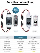
I found that the 1000V/30A seems to have some advantages:
HT3-DZ47Z-30As.jpg
It is DC-only and the Internal Spatial spec is listed as Bigger. Gonna pick one up.

There's also this
Which includes SPDs — is that something I need at this point? In the diagram there is a ground connection from the SPD, I don't currently have a ground for this project (unless connecting to the house ground would work — I'm assuming no, and I don't understand the implications).
 
What gloves are you using?
Mine are over 20 years old. They are below the "Class 0" electricians gloves. Mine are probably rated to just 500 volts, but thy bend easy fo working on small stuff. These are about as close as I could find.


Those are for working on up to 750 volt DC and 300 volt AC
 
What breaker do you recommend? I'm having a tough time finding one, HD/Lowes don't seem to have DC stuff and on Amazon I'm not finding UL-listed ones, just some that say CE. Hard to discern quality, money is not a huge factor at this stage, it's for safety so I'd rather get a good one that people here recommend.

While at it, what Class-T fuse do y'all recommend? Right now I'd probably be good with 200-300A (my bat is 150Ah but wouldn't mind having the ability to discharge above 1C for special surge situations).

I get mine with holder from Don Rowe. A larger bank such as 4 48V batteries in parallel, I use a 175A T Class on each battery.

To be perfectly clear in my mind, this would only happen when positive is close to negative, correct? Such as when the wires in a circuit breaker, or the CC, are close, but not when I'm plugging/unplugging an MC4 that is energized anywhere in the system, as that would be on the same polarity.
To disconnect PV, use an IMO disconnect.
 
To disconnect PV, use an IMO disconnect.
Thanks, these look amazing! There is a highly educational video on the product page which I unfortunately can’t link (at least on mobile, will try on my workstation).

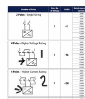
I’m having trouble reading the diagrams, here’s what I’m looking at:
IMG_5688.jpeg
I don’t understand the 1 & 2 versions, assuming the breaker is the part my arrow is pointing to in each diagram, I’m only seeing 2 poles. And I’m not understanding why they’re calling it 4 Poles. #1 looks like it’s connected in series, #2 is not clear to me from the diagram how that’s a drawing of a parallel setup. I’m just not getting where the 4 poles are when it shows 2 connections to the breaker, just like in the unlabeled 2 Pole version and the top? And then Max Number of Strings is 1 for all of them anyway.. 🤷‍♂️

I’ll be running 3S2P, the top “2 Poles” versions should be fine right? I’d just like to understand what I’m looking at in those diagrams, what I’m missing.
 
Thanks, these look amazing! There is a highly educational video on the product page which I unfortunately can’t link (at least on mobile, will try on my workstation).

I’m having trouble reading the diagrams, here’s what I’m looking at:
View attachment 207235
I don’t understand the 1 & 2 versions, assuming the breaker is the part my arrow is pointing to in each diagram, I’m only seeing 2 poles. And I’m not understanding why they’re calling it 4 Poles. #1 looks like it’s connected in series, #2 is not clear to me from the diagram how that’s a drawing of a parallel setup. I’m just not getting where the 4 poles are when it shows 2 connections to the breaker, just like in the unlabeled 2 Pole version and the top? And then Max Number of Strings is 1 for all of them anyway.. 🤷‍♂️

I’ll be running 3S2P, the top “2 Poles” versions should be fine right? I’d just like to understand what I’m looking at in those diagrams, what I’m missing.
So for a single string you'd want the two pole version, for two strings the four pole version etc. I have a 4 pole clone version so I can disconnect two strings to two different sccs.
 
Thanks, these look amazing! There is a highly educational video on the product page which I unfortunately can’t link (at least on mobile, will try on my workstation).

I’m having trouble reading the diagrams, here’s what I’m looking at:
View attachment 207235
I don’t understand the 1 & 2 versions, assuming the breaker is the part my arrow is pointing to in each diagram, I’m only seeing 2 poles. And I’m not understanding why they’re calling it 4 Poles. #1 looks like it’s connected in series, #2 is not clear to me from the diagram how that’s a drawing of a parallel setup. I’m just not getting where the 4 poles are when it shows 2 connections to the breaker, just like in the unlabeled 2 Pole version and the top? And then Max Number of Strings is 1 for all of them anyway.. 🤷‍♂️

I’ll be running 3S2P, the top “2 Poles” versions should be fine right? I’d just like to understand what I’m looking at in those diagrams, what I’m missing.
There isn't a breaker, it is a PV disconnect engineered and designed specifically for breaking high voltage PV. It breaks both negative and positive.

The wiring for a 4 pole is 1 goes to 2, 3 to 4, 5 to 6 and 7 to 8. The reason for this is due to the arc chutes and the rotary snap action.

Johnny explains it in this video.
 
So for a single string you'd want the two pole version, for two strings the four pole version etc. I have a 4 pole clone version so I can disconnect two strings to two different sccs.
Yep, clear on that, just confused by the 2nd and 3rd diagrams in the pic I posted. It says 4 Poles for both, but it also says Max No. Strings: 1 for both, and also to me it looks like the switches in each drawing only have 2 poles.. why would you ever even have 4 poles for 1 string?
It may be simpler for you to get an mc4 version here:
That looks really good actually!
There isn't a breaker, it is a PV disconnect engineered and designed specifically for breaking high voltage PV. It breaks both negative and positive.

The wiring for a 4 pole is 1 goes to 2, 3 to 4, 5 to 6 and 7 to 8. The reason for this is due to the arc chutes and the rotary snap action.

Johnny explains it in this video.
Thanks, that was great to see! I won't be getting a 4 pole version, I'm just confused by their diagrams, to me what is labeled 4 Poles in the diagrams only looks like 2 poles. I'd be getting the first option anyway, these two options which I'm confused about are their special "Higher Voltage/Current Rating" versions which I don't think I need.
 
Yep, clear on that, just confused by the 2nd and 3rd diagrams in the pic I posted. It says 4 Poles for both, but it also says Max No. Strings: 1 for both, and also to me it looks like the switches in each drawing only have 2 poles.. why would you ever even have 4 poles for 1 string?

That looks really good actually!

Thanks, that was great to see! I won't be getting a 4 pole version, I'm just confused by their diagrams, to me what is labeled 4 Poles in the diagrams only looks like 2 poles. I'd be getting the first option anyway, these two options which I'm confused about are their special "Higher Voltage/Current Rating" versions which I don't think I need.
They series them to get from 16 to 32A capability on some models I believe.
 
why would you ever even have 4 poles for 1 string?

If string voltage exceeds what a single pole can handle, multiple poles in series take care of it. Sometimes 2, 4, even 6 poles in series.

For PV strings it is useful to isolate both PV+ and PV-, so 2 poles for up to about 300V string, or 4 poles for 600V.
 
If string voltage exceeds what a single pole can handle, multiple poles in series take care of it. Sometimes 2, 4, even 6 poles in series.
I apologize but I’m having a hard time understanding how the actual connections are made. Does one wire per polarity come from the single string to the switch? How is it wired then, let’s say the switch has 4 poles, 2 per polarity? Is it somehow split then fed thru to poles (per polarity), or?

I think this is the mystery and I’m close to figuring it out conceptually :)
 
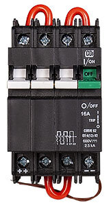
Here's a breaker from Midnight Solar with four 150V poles ganged together:


It could use all four wired in series (as shown) to interrupt 600V PV string that is grounded on one end. For an ungrounded string feeding a transformerless inverter, I would use 2 poles in series for PV+, the other two for PV-.

Here's another model with 2 poles also rated 600V, each pole must be good for 300V:


That is shown with a jumper connecting the two in series, so opens a 600V string at one end.
I would remove the jumper and run PV+/PV- each through one pole for an ungrounded string.
 
Here's a breaker from Midnight Solar with four 150V poles ganged together:


It could use all four wired in series (as shown) to interrupt 600V PV string that is grounded on one end. For an ungrounded string feeding a transformerless inverter, I would use 2 poles in series for PV+, the other two for PV-.
I'm missing something obvious here, to my mind, the way this is shown
mnepv600_web.jpg
if the PV input would be connected on the bottom terminals, the only two available, it would create a short when the switch is thrown on.

Maybe there is some trickery where the top left goes to bottom right, like the IMO, but regardless of how it is, if you have two inputs, a positive and a negative, there should be two outputs to go to your CC, no matter how many poles and jumpers. I'm banging my head against the wall because I don't understand how this works from a wiring perspective :( The little diagram on the switch is very low rez, and I both can't make it out well and don't understand it.
 
I’m having trouble reading the diagrams, here’s what I’m looking at:
View attachment 207235
I don’t understand the 1 & 2 versions, assuming the breaker is the part my arrow is pointing to in each diagram, I’m only seeing 2 poles. And I’m not understanding why they’re calling it 4 Poles. #1 looks like it’s connected in series, #2 is not clear to me from the diagram how that’s a drawing of a parallel setup. I’m just not getting where the 4 poles are when it shows 2 connections to the breaker, just like in the unlabeled 2 Pole version and the top? And then Max Number of Strings is 1 for all of them anyway.. 🤷‍♂️
You need to define string voltage, amperage and series/parallel.

That decides what IMO is needed. You read the guide? https://downloads.imopc.com/solar-isolator-selection-guide.pdf

I’ll be running 3S2P, the top “2 Poles” versions should be fine right? I’d just like to understand what I’m looking at in those diagrams, what I’m missing.
Are you combining strings before the IMO, in the IMO or after the IMO?

That makes a difference. Before the IMO, you need a 2 pole IMO, just a negative and a positive. In the IMO, you need a 4 pole with jumpers in place so both negatives get combined and both positives. After the IMO, you need a 4 pole that keeps both strings separate, 2 negatives and 2 positives.

As for the reason why different offerings with different number of poles, it comes down to voltage (usually limited by SCC) and amperage (possibly limited by SCC but also panel ISC and what AWG wire will be run from point A to point B).

For example, running 2 strings of 10AWG 400 feet to an IMO that will combine those strings into parallel will be cheaper than running 1 string of 8AWG 400 feet. I know, because I've run the figures. Or, maybe the 10AWG strings will be combined after the IMO, so a larger number of poles is needed.
 
Of course - that configuration works as a SPST switch, good for 600V. Switch PV+ only.
If you want to switch both PV+ and PV-, remove the red jumper in middle, bottom of picture.

Good news is, IF you connect polarity correctly, it is load-break rated.
(If not, be sure to make a video and post it under Up In Smoke!)
 
Back
Top