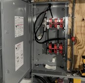
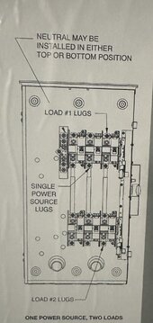
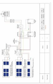
I’m getting a Sol-Ark 15k and looking to install this double throw switch to switch from grid -off- solar. I’m confused as to how to wire it up. I think I should’ve bought the 3 pole to have an isolated N from researching on here. Can I still use this box? If so, how would I go about the wiring because the diagram shows a single power source lugs in the middle which I do not have.


You are using an out of date browser. It may not display this or other websites correctly.
You should upgrade or use an alternative browser.
You should upgrade or use an alternative browser.
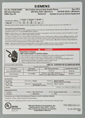
200 amp double throw
- Thread starter Bricktop
- Start date
BentleyJ
Solar Wizard
To make it easier, you can think of the "Single Power Source" lugs as Common which can be switched or connected to lugs #1 or #2 by changing the position of the lever. That type of switch is Bi-directional. Don't get hung up on Line/Load or Input/Output terminology.
If you post a simple drawing of the components and proposed connections we could be more specific.
If you post a simple drawing of the components and proposed connections we could be more specific.
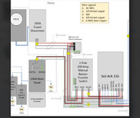
I’m copying this layoutTo make it easier, you can think of the "Single Power Source" lugs as Common which can be switched or connected to lugs #1 or #2 by changing the position of the lever. That type of switch is Bi-directional. Don't get hung up on Line/Load or Input/Output terminology.
If you post a simple drawing of the components and proposed connections we could be more specific.
Attachments
BentleyJ
Solar Wizard
That looks good.
Item #2 on the wire gauge chart lists 2/0 tinned copper. Depending on your inspector, 3/0 may be required for 200A or you could derate the fuses in the 200A disconnect for the 2/0 wire.
Item #2 on the wire gauge chart lists 2/0 tinned copper. Depending on your inspector, 3/0 may be required for 200A or you could derate the fuses in the 200A disconnect for the 2/0 wire.
400bird
Solar Wizard
Just hold the diagram sideways and do the same connection order shown. Grid and SolArk on opposite ends, output/loads in the middle.I’m copying this layout
I think the ground-neutral bonding should be at the 200 amp fuse disconnect. But I’ll wait for “ the man of few words” to chime in.I’m copying this layout
400bird
Solar Wizard
I think you've got to say his name 3 timesI think the ground-neutral bonding should be at the 200 amp fuse disconnect. But I’ll wait for “ the man of few words” to chime in.
@timselectric while you make a wish on a mud puddle or something like that.
But, you'll see the neutral doesn't go into the switch on SolArk's drawing. Looks right to me. However, Tim's the king of that subject.
Hedges
I See Electromagnetic Fields!
- Joined
- Mar 28, 2020
- Messages
- 20,703
I don't think it is necessary to switch neutral.
Neutral should follow path and be in same conduit as L1/L2 where current is flowing. I would even make a loop out of N if necessary to achieve that, but having multiple circuits enter and exit through same conduit could avoid that, and having all three circuits enter the switch through a single branch would mean N doesn't even need to go through it. (Similar to a light switch, just gets hot and switched, not neutral.)
Neutral should follow path and be in same conduit as L1/L2 where current is flowing. I would even make a loop out of N if necessary to achieve that, but having multiple circuits enter and exit through same conduit could avoid that, and having all three circuits enter the switch through a single branch would mean N doesn't even need to go through it. (Similar to a light switch, just gets hot and switched, not neutral.)
jmsandrsn
New Member
I have a question based on the layout in Post #3 above. If the inverter goes out, you would switch to to the grid using the transfer switch. It looks like the grid input on the inverter would still be hot based on the polaris tap connection. Could that introduce any backfeed that might further harm the inverter?
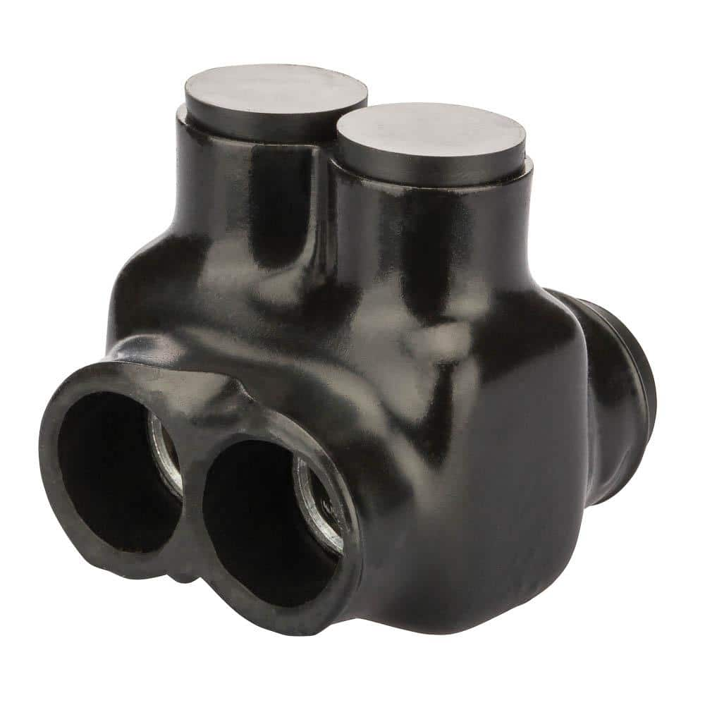
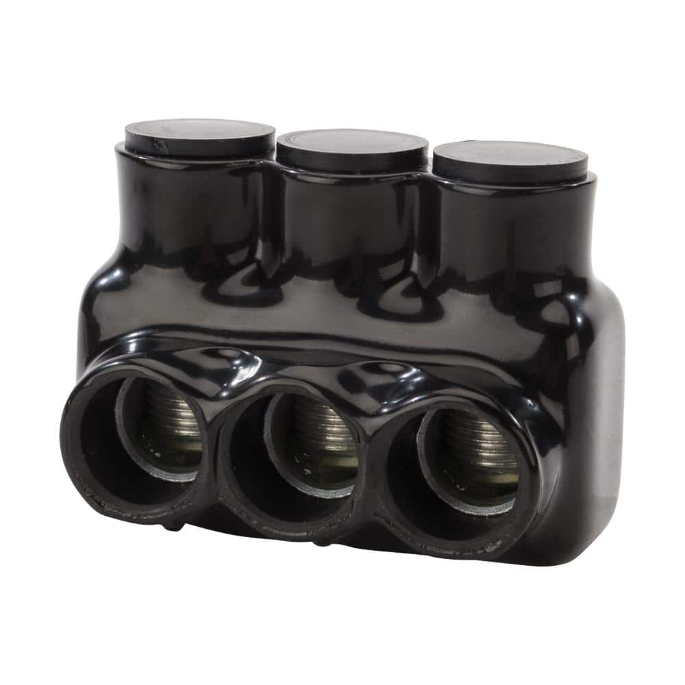
I couldn't find a polaris connector for use with 4/0 wire. Does anyone have a link to this or perhaps another brand if there is not one from polaris?
I might be able to get some Southwire 4/0 4/0 4/0 2/0 feeder cable (MHF) for about $2.50 per foot. I was thinking of using this for running between switch, fuse panel, inverter, and tap connectors (original SER cable will still come in from the meter). Any issues with using the MHFcable in this case. MHF can be used inside provided it is in conduit.
Hedges
I See Electromagnetic Fields!
- Joined
- Mar 28, 2020
- Messages
- 20,703
Here are a couple
I ordered mine through eBay sellers.
Fits 6 awg up to 250 MCM.
I use some 4-hole ones. With 3/0 cable I am able to fit insulated wire through the hole, strip a section in middle of wire, and attach Polaris there (don't know if 4/0 insulation also fits). That way the tap is in middle of wire. A 2-hole Polaris could connect 4 things. I'm connecting one main breaker to three other sub-panels or switches, and have a couple taps left for future expansion.
Polaris 250 MCM - 6 AWG Insulated Tap Connector, Black IT-250B - The Home Depot
IT series insul-tap connectors are suitable for connecting 2-wires. Which are provided with open wire entry ports on both sides of the connector, which allows for access from either side. This style is
www.homedepot.com
Polaris 250 MCM-6 AWG Bagged Insulated Multi-Tap Connector, Black IPL250-3B - The Home Depot
IPL insulated multi-tap connectors are suitable for connecting 3-wires. Will not support combustion. Cold temperature rated to -45°C. Dual rated for use with copper and/or aluminum cables. 600-Volt. Not
www.homedepot.com
I ordered mine through eBay sellers.
Fits 6 awg up to 250 MCM.
I use some 4-hole ones. With 3/0 cable I am able to fit insulated wire through the hole, strip a section in middle of wire, and attach Polaris there (don't know if 4/0 insulation also fits). That way the tap is in middle of wire. A 2-hole Polaris could connect 4 things. I'm connecting one main breaker to three other sub-panels or switches, and have a couple taps left for future expansion.
jmsandrsn
New Member
Thanks very much for pointing out the one that support 250 mcm. After further research, I found out that 4/0 wire is equivalent to approximately 212 mcm, so 250 mcm should be more than big enough.
Just to clarify, you are saying that the first connector from your Home Depot link can support 4 wires? After reading about the product, I thought that the 2 port model would only support 2 connections and you should not use the position directly in line with another positions being used (maybe I'm incorrect). Are you saying that there is enogh room so that the lug will come down and secure both wires?
Just to clarify, you are saying that the first connector from your Home Depot link can support 4 wires? After reading about the product, I thought that the 2 port model would only support 2 connections and you should not use the position directly in line with another positions being used (maybe I'm incorrect). Are you saying that there is enogh room so that the lug will come down and secure both wires?
I have a question based on the layout in Post #3 above. If the inverter goes out, you would switch to to the grid using the transfer switch. It looks like the grid input on the inverter would still be hot based on the polaris tap connection. Could that introduce any backfeed that might further harm the inverter?
I couldn't find a polaris connector for use with 4/0 wire. Does anyone have a link to this or perhaps another brand if there is not one from polaris?
I might be able to get some Southwire 4/0 4/0 4/0 2/0 feeder cable (MHF) for about $2.50 per foot. I was thinking of using this for running between switch, fuse panel, inverter, and tap connectors (original SER cable will still come in from the meter). Any issues with using the MHFcable in this case. MHF can be used inside provided it is in conduit.
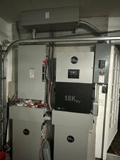
I did a similar setup but wanted the option to isolate the inverter so I put a disconnect inline.
Attachments
Hedges
I See Electromagnetic Fields!
- Joined
- Mar 28, 2020
- Messages
- 20,703
Thanks very much for pointing out the one that support 250 mcm. After further research, I found out that 4/0 wire is equivalent to approximately 212 mcm, so 250 mcm should be more than big enough.
Just to clarify, you are saying that the first connector from your Home Depot link can support 4 wires? After reading about the product, I thought that the 2 port model would only support 2 connections and you should not use the position directly in line with another positions being used (maybe I'm incorrect). Are you saying that there is enogh room so that the lug will come down and secure both wires?
Only two wires for the dual Polaris. Not many terminals are "listed" for two wire under a single screw (set-screw wire nuts being one.)
But each wire has two ends. By stripping about 1" of insulation off the middle of a wire, I am able to slip 3/0 (or other like 2 awg) through and connect Polaris in the middle. Leaving two ends. I'm not sure if 4/0 would fit, depends on OD of insulation.
Only some models of Polaris have thru-hole and plugs for both sides, make sure you get what you want.
In the picture below, I've fed 2 awg through each Polaris (also breaker socket lugs, which I did with 6 awg green and 4 awg solid bare too.)
At the moment, 3/0 stub terminates in Polaris. After "cut and swing" of utility drop I'll transfer circuits from existing main panel to new sub panel, then replace main panel with a 200A sub panel and feed 2/0 from it through Polaris to main breaker.

jmsandrsn
New Member
Thanks everyone!
The Onan 200 amp and 400 amp transfer switches I’ve seen at tower sites switch the neutral. Generac residential switches do not. I don’t see the need to switch the neutral but there must be a reason for it. It’s a good question.
Last edited:
jmsandrsn
New Member
I did a similar setup but wanted the option to isolate the inverter so I put a disconnect inline.
Thanks for attaching the diagram. What size junction box did you use and/or do you know the model# or have a link? Did you use Polaris connectors or something similar?
Also, what is the model# for your transfer switch? Is there any reason why you couldn't use the Polaris connectors inside the transfer switch box (other than it might limited room)?


Similar threads
- Replies
- 21
- Views
- 1K
- Replies
- 15
- Views
- 978
- Replies
- 6
- Views
- 499
- Replies
- 1
- Views
- 282
- Replies
- 52
- Views
- 3K