


You are using an out of date browser. It may not display this or other websites correctly.
You should upgrade or use an alternative browser.
You should upgrade or use an alternative browser.
2000w, 24v solar system
- Thread starter guidecca
- Start date
I will use a battery protect on the DC side for under-voltage protection by DC appliances on the battery bank? DC appliances could draw down the battery bank without one. Also, what size wire should I use? My order for 1/0 AWG arrived today and I think it is way too big. Maybe 1 or 2 AWG would work better. I have 6 awg (five feet) and 8 awg (five feet) and pre-made 1/0 AWG and connectors (four feet). How do I wire up a shore power connection?
I am using 1/0 for my 24V, 2000W inverter.I will use a battery protect on the DC side for under-voltage protection by DC appliances on the battery bank? DC appliances could draw down the battery bank without one. Also, what size wire should I use? My order for 1/0 AWG arrived today and I think it is way too big. Maybe 1 or 2 AWG would work better. I have 6 awg (five feet) and 8 awg (five feet) and pre-made 1/0 AWG and connectors (four feet). How do I wire up a shore power connection?
For other wiring:
14 AWG protected by 20A fuse or circuit breaker
12 AWG protected by 30A fuse or circuit breaker
10 AWG protected by 40A fuse or circuit breaker
8 AWG protected by 50A fuse or circuit breaker
Shore power should have it's own circuit breaker. You have to decide what you want to be able to plug into. I am using a 30A, 115V shore power connection wired with 10 AWG wire protected by a 30A circuit breaker (I am a firm believer in overkill).
You can use a twist lock power inlet (google for RV 30A Power inlet) if cost is an issue. I am using SmartPlug for my system because cost is not an issue for me.
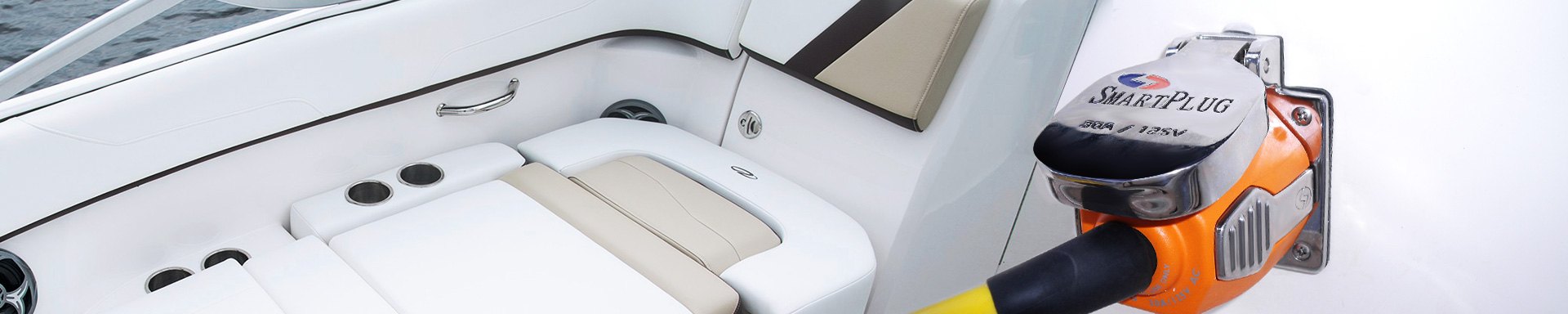
SmartPlug™ | Marine 30A & 50A Power Cords, Connector Kits, Weatherproof Covers - BOATiD.com
Discover a wide selection of boat parts, accessories, and related products that we source from SmartPlug and many other trusted brands. We have great prices on boating and marine products.
-Edit-
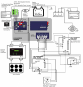
I have attached my latest system drawing if you want to see precisely what I am doing.
Attachments
Thank you for the wire/fuse information and your diagram. Just finished fixing a gas furnace for $40.00, but that was easy compared to this. Nothing to lose when fixing a broken furnace. Here, none of the components are broken, yet. Have ever used these: Blue Sea Systems MRBF Surface and Terminal Mount Fuse Block, https://www.amazon.com/gp/product/B0753F35Q8/ref=ox_sc_act_title_1?smid=ATVPDKIKX0DER&psc=1? I saw them on another system here in the forum. I am thinking about adding the van battery to charge the Battle Born batteries while driving.
I understand how to connect the solar charge controller to the inverter. I have a 12/2 wiring assembly and a panel interface connector with a 15 amp circuit breaker and GFCI AC outlet to access AC power. I understand how to connect the battery bank to the inverter. I do not understand how to charge the battery bank from the inverter.
I understand how to connect the solar charge controller to the inverter. I have a 12/2 wiring assembly and a panel interface connector with a 15 amp circuit breaker and GFCI AC outlet to access AC power. I understand how to connect the battery bank to the inverter. I do not understand how to charge the battery bank from the inverter.
This is the part I have always struggled to understand about your plan as well.
If you drew a simple visual representation / diagram of what you are planning it would be much easier for me (and probably others) to follow along / give meaningful feedback.
Last edited:
I understand how to connect the solar charge controller to the inverter. I have a 12/2 wiring assembly and a panel interface connector with a 15 amp circuit breaker and GFCI AC outlet to access AC power. I understand how to connect the battery bank to the inverter. I do not understand how to charge the battery bank from the inverter.
The inverter documentation should cover this.
I'm sorry, my comment 100% missed the mark. I was confusing some of the details of your situation with another forum member. Disregard 100% of the above.This is the part I have always struggled to understand about your plan as well.
If you drew a simple visual representation / diagram of what you are planning it would be much easier for me (and probably others) to follow along / give meaningful feedback.
edit: I imagine that me asking you to draw a diagram... when I helped you draw your diagram a few pages back... was rather perplexing ?

You have the EVO 2224 correct?
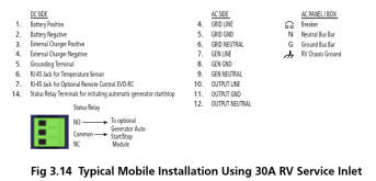
Here is the manual
Page 57-58 describe and show a 'typical' mobile installation. Its not the most beginner friendly diagram, but it may help clarify some things.
Here is the manual
Page 57-58 describe and show a 'typical' mobile installation. Its not the most beginner friendly diagram, but it may help clarify some things.
Attachments
and for what its worth, I think the Samlex schematic probably makes it more complicated than it needs to be.
I am using 1/0 for my 24V, 2000W inverter.
For other wiring:
14 AWG protected by 20A fuse or circuit breaker
12 AWG protected by 30A fuse or circuit breaker
10 AWG protected by 40A fuse or circuit breaker
8 AWG protected by 50A fuse or circuit breaker
Shore power should have it's own circuit breaker. You have to decide what you want to be able to plug into. I am using a 30A, 115V shore power connection wired with 10 AWG wire protected by a 30A circuit breaker (I am a firm believer in overkill).
You can use a twist lock power inlet (google for RV 30A Power inlet) if cost is an issue. I am using SmartPlug for my system because cost is not an issue for me.
SmartPlug™ | Marine 30A & 50A Power Cords, Connector Kits, Weatherproof Covers - BOATiD.com
Discover a wide selection of boat parts, accessories, and related products that we source from SmartPlug and many other trusted brands. We have great prices on boating and marine products.www.boatid.com
-Edit-
I have attached my latest system drawing if you want to see precisely what I am doing.
Would you recommend this for 12 and 14 gage wire? https://www.amazon.com/gp/product/B...d506a71e728ebcb62ac&language=en_US&th=1&psc=1I am using 1/0 for my 24V, 2000W inverter.
For other wiring:
14 AWG protected by 20A fuse or circuit breaker
12 AWG protected by 30A fuse or circuit breaker
10 AWG protected by 40A fuse or circuit breaker
8 AWG protected by 50A fuse or circuit breaker
Shore power should have it's own circuit breaker. You have to decide what you want to be able to plug into. I am using a 30A, 115V shore power connection wired with 10 AWG wire protected by a 30A circuit breaker (I am a firm believer in overkill).
You can use a twist lock power inlet (google for RV 30A Power inlet) if cost is an issue. I am using SmartPlug for my system because cost is not an issue for me.
SmartPlug™ | Marine 30A & 50A Power Cords, Connector Kits, Weatherproof Covers - BOATiD.com
Discover a wide selection of boat parts, accessories, and related products that we source from SmartPlug and many other trusted brands. We have great prices on boating and marine products.
-Edit-
I have attached my latest system drawing if you want to see precisely what I am doing.
I don't know anything about the seller/store, but the brand--Ancor--is reputable, UL listed, and a good temperature rating (105*C). So yes!
That would be fine for DC, but not for AC, there is no ground wire (AC needs 3 wires). The wire itself looks great.Would you recommend this for 12 and 14 gage wire? https://www.amazon.com/gp/product/B...d506a71e728ebcb62ac&language=en_US&th=1&psc=1
Here is similar Marine Wire (different company but reputable supplier) for AC, sold by the foot
 baymarinesupply.com
Marine Grade Flat Triplex Wires
Triplex wire for marine and other DC applications. Tinned, stranded conductors resist corrosion and vibration for use in harsh environments, and extended service in normal applications.
baymarinesupply.com
My favorite vendor PKYS is slightly cheaper. Shipping cost could drive the decision one way or the other.Here is similar Marine Wire (different company but reputable supplier) for AC, sold by the foot
Marine Grade Flat Triplex Wires
Triplex wire for marine and other DC applications. Tinned, stranded conductors resist corrosion and vibration for use in harsh environments, and extended service in normal applications.
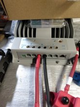
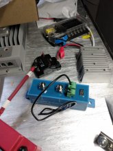
1) Anyone know what input and output refer to with a disconnect switch between battery bank and inverter charger?
2) Also, the two poles on the Epever Tracer Charge Controller with a "light bulb" symbol; do they connect to the DC fuse block via the 25A switch and the Victron Energy Battery Protect and the 24V to 12V Converter?
3) Which way does the battery protect input and output face; "out" and "in" are the two choices? I'm thinking "out" would be the 12V side and "in" would be the 24V side.
Attachments
I would guess input is where you connect the battery side, output is where you connect the load side.1) Anyone know what input and output refer to with a disconnect switch between battery bank and inverter charger?
Blue Sea M-Series Install Guide
I would guess the light bulb is the load output for the SCC. If you are using a battery protect it may or may not be useful to use the load output.2) Also, the two poles on the Epever Tracer Charge Controller with a "light bulb" symbol; do they connect to the DC fuse block via the 25A switch and the Victron Energy Battery Protect and the 24V to 12V Converter?
Epever Tracer (BN) Manual (is this the model you have?)
The manual shows many wiring examples, the battery would be connected to 'in' and out would go to the loads, or if you were using it with a charger it would be the opposite.3) Which way does the battery protect input and output face; "out" and "in" are the two choices? I'm thinking "out" would be the 12V side and "in" would be the 24V side.
Battery Protect Manual
I posted the manuals because I'm not a reliable explainer of any of these specifics, I don't own any of these devices, so you are now more familiar with them than I am, And also because it would be worth your while to familiarize yourself with it. Lots of good info for your SCC and the battery protect contained in the documentation.
Last edited:
The batteries are sending 24V to the 24V to 12V converter. Is the Solar CC "load output" sending 12V?If you are using a battery protect it may or may not be useful to use the load output.
The battery protect is supposed to keep the DC loads from draining the battery at some predetermined level. Maybe there is a conflict.
Last edited:
I believe the load output should output the same voltage as the CC outputs to the battery bank.The batteries are sending 24V to the 24V to 12V converter. Is the Solar CC "load output" sending 12V?
I have not owned or researched a CC with separate load outputs, but I can't imagine it would output any other voltage by default.
I'm not sure there would be any conflict but it may be redundant.The battery protect is supposed to keep the DC loads from draining the battery at some predetermined level. Maybe there is a conflict.
My thinking is that if you use the battery protect, don't connect through the load output (which is an optional feature). Or you could posisbly return or sell the battery protect and use the load output for low voltage disconnect if it can be used that way, and can carry enough current for your DC loads (check the manual).
You should either check the manual or get a second/third opinion. I've never really bothered learning about the particulars of the load output functionality of SCC's before.
Similar threads
- Replies
- 4
- Views
- 158
- Replies
- 4
- Views
- 639
- Replies
- 15
- Views
- 292
- Replies
- 13
- Views
- 504
- Replies
- 4
- Views
- 244