chrisski
Solar Boondocker
- Joined
- Aug 14, 2020
- Messages
- 5,192
I am building two 24 volt batteries, each with 8 S 280 ah Eve Cells. I've decided on two Overkill 8S BMS 24 volt 100 amps. I have a SAMLEX 3000 watt inverter, of which, I do not plan on running moe than 2000 watt loads, like a microwave for several minutes a day. I expect that and other loads to max out at 75 amps from the batteries. Looking for feedback.
I have quite a bit of time until these cells show up, so I've started to plan the build which will be placed in a 2' by 2' battery slide out tray. Below is a mostly to scale done by power point drawing of the wiring.

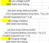
My 24 volt inverter will see a variety of voltages, from 28 volts charging, to 24 volts from the battery, to as low as 20 volts if the inverter is pulling a lot of power from the batteries. So when the panels are pushing amps into the battery at 28 volts and the inverter is running its full 3000 watts, I could see 123 amps from the battery with inverter losses. But to push the inverter to the same 3000 watts if the voltage is only 20 volts, I could see 172 amps from the battery with inverter losses. So to fuse for that 172 amps with some headroom, I come out with a 215 amps, of which available is a 200 amp class T or a 225 amp Class T. I'm going with the 225 amp class T.
When choosing the wires sizes, some were pretty easy like getting the two pair 8 AWG upgrade for the Overkill BMS. Not much of a choice about what to install. At an inverter DC cutoff voltage of 20, this is some of the data for voltage loss I could expect at max continuous production of 100 amps for these Overkill wires:

For the rest of the build, I compared both Ampacity of a wire to Voltage loss:

Now from each positive battery to the positive busbar opted for 2 AWG wires because ampacity is less than I expect to see.

After that, I looked at ampacity of the wires and wire loss, and ampacity was more of a factor than voltage loss. Joining the batteries became a bit of a search, especially because I'm such a fan of Blue Sea, but at $100 for a busbar, I just happened to have a 48 volt 250 amp pair of 4 post busbars left over from my last build. Not Blue Sea but the price is right and they are in specs.
Once, joined at the Battery bus bar, there could be 200 amps continuous coming from the batteries, even though now I never plan to see more than 75 amps total. To reach from the battery busbars to the main bus bars, I have up to 10' of cable to run. Probably less than 4 feet on the positive side although this will terminate at a fuse prior to the busbar and 6 feet on the negative side, although it actually will terminate at the a Shunt located before the busbar. Based off the ampacity table, I'm planning on using 2/0 wire. This is some of the voltage loss data:

Out of everything I listed, I did not quite make the ampacity of 200 amp with the 2/0 wire, so I will may drop the fuse to 200 amps, or more likely use the remaining 4/0 wire I have and I'd be comfortably in the ampacity.
Part of a possible expansion would be adding a third battery bank, but honestly I do not see a need for so much power in my RV. Unless I get a functional solar AC, which is my 2022 project.....
I have quite a bit of time until these cells show up, so I've started to plan the build which will be placed in a 2' by 2' battery slide out tray. Below is a mostly to scale done by power point drawing of the wiring.
My 24 volt inverter will see a variety of voltages, from 28 volts charging, to 24 volts from the battery, to as low as 20 volts if the inverter is pulling a lot of power from the batteries. So when the panels are pushing amps into the battery at 28 volts and the inverter is running its full 3000 watts, I could see 123 amps from the battery with inverter losses. But to push the inverter to the same 3000 watts if the voltage is only 20 volts, I could see 172 amps from the battery with inverter losses. So to fuse for that 172 amps with some headroom, I come out with a 215 amps, of which available is a 200 amp class T or a 225 amp Class T. I'm going with the 225 amp class T.
When choosing the wires sizes, some were pretty easy like getting the two pair 8 AWG upgrade for the Overkill BMS. Not much of a choice about what to install. At an inverter DC cutoff voltage of 20, this is some of the data for voltage loss I could expect at max continuous production of 100 amps for these Overkill wires:
For the rest of the build, I compared both Ampacity of a wire to Voltage loss:
Now from each positive battery to the positive busbar opted for 2 AWG wires because ampacity is less than I expect to see.
After that, I looked at ampacity of the wires and wire loss, and ampacity was more of a factor than voltage loss. Joining the batteries became a bit of a search, especially because I'm such a fan of Blue Sea, but at $100 for a busbar, I just happened to have a 48 volt 250 amp pair of 4 post busbars left over from my last build. Not Blue Sea but the price is right and they are in specs.
Once, joined at the Battery bus bar, there could be 200 amps continuous coming from the batteries, even though now I never plan to see more than 75 amps total. To reach from the battery busbars to the main bus bars, I have up to 10' of cable to run. Probably less than 4 feet on the positive side although this will terminate at a fuse prior to the busbar and 6 feet on the negative side, although it actually will terminate at the a Shunt located before the busbar. Based off the ampacity table, I'm planning on using 2/0 wire. This is some of the voltage loss data:
Out of everything I listed, I did not quite make the ampacity of 200 amp with the 2/0 wire, so I will may drop the fuse to 200 amps, or more likely use the remaining 4/0 wire I have and I'd be comfortably in the ampacity.
Part of a possible expansion would be adding a third battery bank, but honestly I do not see a need for so much power in my RV. Unless I get a functional solar AC, which is my 2022 project.....
Last edited: