diy solar

diy solar

2x 8s 24V configuration

Electry

New Member
Joined
Jan 29, 2022
Messages
12
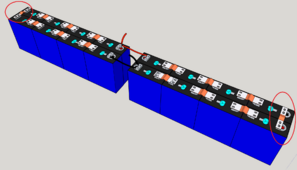
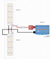
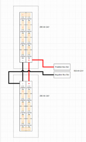
I'm trying to build 2 battery packs each consisting of 8s 280Ah cells and want the battery packs in parallel. I have added the images. Do the connections look correct? Will the load be distributed between two packs equally? Also I'm questioning the cell bus bars (marked in red circle). Could there be a problem since they are 2x smaller than all other cell bus bars? Thanks.

1718824628670.png
1718824698670.png
 
All looks good. The circled bars are fine as they are in series with the others and match battery to battery.
Balance will never be perfectly perfect but this configuration is as close as it will get.
 
balance of current between the two will never be 100% spot on, but the total capacity of the two will add up.

Are you doing two batteries for more peak current capability or just more storage?
 
I'm trying to build 2 battery packs each consisting of 8s 280Ah cells and want the battery packs in parallel. I have added the images. Do the connections look correct? Will the load be distributed between two packs equally? Also I'm questioning the cell bus bars (marked in red circle). Could there be a problem since they are 2x smaller than all other cell bus bars? Thanks.

View attachment 223187
View attachment 223188
Since you already have a busbar, why not connect each one separately to the busbar.
What about fuses / breakers?

If you connect each one separately, you will be able to disconnect each battery separately, should you need to do some maintenance on one, without disrupting overall power to your system.

Personally, I have two 8s packs, each with its own MBRF fuse (mounted on the terminal), each wired to a DC breaker, then each breaker to the busbar, from there to the inverter, etc...
 
balance of current between the two will never be 100% spot on, but the total capacity of the two will add up.

Are you doing two batteries for more peak current capability or just more storage?
Mostly for more storage, but also because I can use smaller BMS (like 100A for each battery bank instead of 200A). Most likely I will not exceed 2400W either way so I think it will be pretty safe even if one battery bank fails.

Since you already have a busbar, why not connect each one separately to the busbar.
What about fuses / breakers?

If you connect each one separately, you will be able to disconnect each battery separately, should you need to do some maintenance on one, without disrupting overall power to your system.

Personally, I have two 8s packs, each with its own MBRF fuse (mounted on the terminal), each wired to a DC breaker, then each breaker to the busbar, from there to the inverter, etc...
If connecting to busbars, I need both positive and negative wires for both battery banks to be equal length (from busbars to battery banks)? Just for example: there are two positive wires (each 2m length) from positive busbar to each battery bank. As for the two negative wires, each of them could be 3 meters? In other words, positive wire length could be different length than negative, they should only match all posives and negatives wires respectively? I guess balance between the batteries will be improved than my current planned setup (diagonal connection), or it's only the case with 3 and more battery banks?

With the current planned setup I think I save a bit of wires + I don't need separate busbars just for the batteries (small weight savings), but thanks for your suggestion. If I can achieve better balance between two battery banks I might go with your suggestion.

I'm planning to use MBRF fuses on each battery bank positive terminal + one separate fuse on main positive wire (still thinking if that's worth it when each battery will be fused anyways) which then goes to BlueSea battery isolator switch and then to the Victron Lynx.

I will put these batteries in RV so I need to save weight where I can. I have updated the schema so it makes more sense now.

1718875688291.png
 
Last edited:
1) LFP is NOT 3.7V it is 3.2V Nominal.
- Allowable Voltage Range that does not harm the cells is 2.500-3.650
- Working Voltage Range that delivers the Spec'd AH is from 3.000-3.400 with nominal being 3.200 (50% SOC)
2) battery Cables should be identical in length (excluding shunts/fuses) and they should be kept together as much as possible to prevent RFI/EMI/
3) Every Battery Pack should be fused. IE a 100A Capable Battery should get at least a 125A fuse. AMPERAGE X 1.25 is the general rule.
4) Battery Packs in Parallel Share/Divide both Charge/Discharge proportionately between them.

Victron Lynx has 2 models, 1 includes Mega-Fuses for each battery connection, these are the Cats Meow in simplicity & reliability.
If using a Switch between BATT & "FUSE" I would suggest a BueSea 9001 Switch, See Here: Look at the 9001E https://www.bluesea.com/products/category/11/41/Manual_Battery_Switches/e-Series

Also you are SHORT CHANGING yourself with a Lame BMS !
These batteries can output 280A for 1 hour & take 140A for 2 hours. They are very capable so don't bother handicapping them, you'll be facepalming later. SERIOUSLY ! Get at least a 200A BMS preferably with Active Balancing and reduce/prevent later stresses. $150 USD +S&H will get you the Latest 200A JKBMS w/ Active Balancing & a 4.3" screen to go with it.
Keep in mind that 24V @ 250A Draw can give you 6000W and everyone virtually always ends up using more than they thought and over time upgrade systems... We see it all the time !

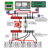
Below is one of my Generic Diagrams for a standard paralleled setup.

Parallel System-setup PNG.png

Here is info regarding LFP you may want to keep handy.
quick-voltage-chart-lfp-jpg.150247
 
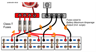
Thanks for great info. Am I thinking correctly?

1. Wires 1, 2, 3 should be equal length; Wires 4, 5, 6 should be equal length;
2. Wires 1, 2, 3 AND 4, 5, 6 don't need to be equal length. For example wires 1, 2, 3 can be 1 meter, wires 4, 5, 6 can be 1.5 meters. I understand that wire 1 can't be 0.5 meter if wires 2, 3 are 1 meter.

As an additional real case scenario, there could be possibility that 1 meter could be enough for all positive wires, but let's say negative bus bar is a bit further away and you need at least 1.5 meters of wire to connect to it. Do I need 1.5 meters positive wire even though 1 meter would be enough, to maintain same length between positive and negative wires? Once again, I understand that lengths should be equal between all postive wires (same for negative wires)

1718881319762.png
 
Simply put 1 through 6 = same length. If there is a fuse/breaker/switch that is "extra" but doesn't count as such.
Be aware that EVERY connection: Lug, fuse, breaker, switch adds to losses & increases resistance "on the line". While each item is not big, cumulatively they add up quite fast.

Also:
NEVER EVER use CCA Wire ! Copper Clad Aluminium is NASTY ASSED SHIT !!! and I am BEING polite !
Always use Fine Strand PURE COPPER wire that is at least rate for 20% more current than you expect. Marine Grade Copper (tined) IS good BUT be certain and get ONLY Quialifiied reputable product.
Many of us use Southwires Royal Excelene wire which is one of the best on the market. I've used it for years.
Always use Tinned or Nickel (more $) plated copper Lugs/Terminals with proper crimping to make an airtight seal, along with quality Heat Shrink Wrap with adhesive/ sealant.

TIP: I evaluated many kinds of wires over the years. I am now in process of refreshing my power house, including battery bank system. With that process I am changing out a "lot" of wire and will be using Kalas FlexWhip Welding Wire, this has finer & more strands that Excelene and has higher ratings for amperage & more. Additionally, also USA Made & "cheaper" than Royal Excelene (easier to get as well). I just got a coil and making up my cabling now. https://www.kalaswire.com/project/flexwhip-welding-cable/

1718882711281.png
 
Thanks for great info. Am I thinking correctly?

1. Wires 1, 2, 3 should be equal length; Wires 4, 5, 6 should be equal length;
2. Wires 1, 2, 3 AND 4, 5, 6 don't need to be equal length. For example wires 1, 2, 3 can be 1 meter, wires 4, 5, 6 can be 1.5 meters. I understand that wire 1 can't be 0.5 meter if wires 2, 3 are 1 meter.

As an additional real case scenario, there could be possibility that 1 meter could be enough for all positive wires, but let's say negative bus bar is a bit further away and you need at least 1.5 meters of wire to connect to it. Do I need 1.5 meters positive wire even though 1 meter would be enough, to maintain same length between positive and negative wires? Once again, I understand that lengths should be equal between all postive wires (same for negative wires)

View attachment 223301
From my understanding, you are correct.
Of course in an ideal world, all wires to all batteries would be the same lengths, but sometimes you need to compromise.

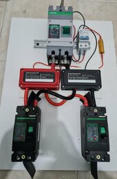
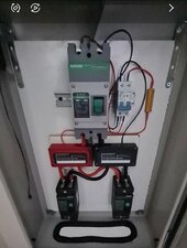
In my setup, overall wire length (positive and negative) are equal for each battery.
Wire length from each battery to each breaker is equal.
But on one battery's breaker, the positive is longer than the negative. On the other, it's the opposite.
So basically each battery has an equal amount of wire resistance. I did this because of busbar placement.
SmartSelect_20240620-142454_Gallery.jpg

I had limited space, because this is installed in a metal enclosure I already had.
SmartSelect_20240620-142356_Gallery.jpg

I've been running like this for over a year now, and it's working fine. Battery charge/discharge is almost perfectly equal between the two batteries.
I say almost, because while both packs use the same type cells (EVE LF105), the cells in one pack are a bit newer than the others.
So small differences exist, but they are negligible.

So to summarize, you want overall wire resistance to be equal for both batteries.
 
My own and many others observations will tell you that even as little as 1" difference in cabling with Packs in Parallel (Rack/ stack or shelf configs) can & will affect the charge rate, that can vary from just a tiny bit to a lot pending on the wire, rating etc. Even Andy @ Andy's garage ran across that reality. Many video's show this and even Will has talked about that a few times. A quite a few (me included) compensated in a way but stepping up the wire gauge BUT that has only limited effects and works for smaller stuff.

By Months End, I'll have 7x280AH in Parallel which is my "final config". Been running parallel packs fr years and with varied AH outputs. At one point, I was running 3x280AH, 2x175AH & 1x100AH and they all ran happily without issues.
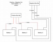
Yes, you are correct regarding cable length difference, but I still think that there could be different length between positive and negatives wires. I attached the image to reflect that. There will be same total cable length for every battery. There shouldn't be difference in resistance since loop for every battery is 3 meters.

1718885290565.png
 
I'm planning to use MBRF fuses on each battery bank positive terminal + one separate fuse on main positive wire (still thinking if that's worth it when each battery will be fused anyways) which then goes to BlueSea battery isolator switch and then to the Victron Lynx.

I will put these batteries in RV so I need to save weight where I can. I have updated the schema so it makes more sense now.

View attachment 223294
I would skip the 200 amp fuse. I also skipped the switch. My battery can be turned off with the BMS app and I would then lift the cable for service. Been connected almost three years now and have yet to lift the cable. Switches are for daily to monthly use IMO.
 
I would skip the 200 amp fuse. I also skipped the switch. My battery can be turned off with the BMS app and I would then lift the cable for service. Been connected almost three years now and have yet to lift the cable. Switches are for daily to monthly use IMO.
Reliant on just the BMS for over voltage protection has been proven to be short sighted.
 
Reliant on just the BMS for over voltage protection has been proven to be short sighted.
Wait what? Fuse is not voltage protection. Each battery has a 100 amp fuse. How will 300 amps get through 2x 100a fuses?
 
Sorry, you’re right I should have said over current protection, brain fart.

You said skip the 200a fuse, I thought you meant skip any fuse at all and just trust the BMS for over current protection.
 

diy solar

diy solar
Back
Top