diy solar

diy solar

3 Phase in US

Do you think that is 220/380Y? In which case, why two different currents?
Or is that 220 delta at 19.7A, alternately wire as 380 delta at 11.4A?

It would be a 6 lead motor (most likely). You can reconfigure the windings to be in either a Delta configuration which would require a 220 volt supply and 19.7 amps. Or it could be wired for 380 in a Y configuration and need 11.4 amps.


SolArk is outside the budget for this. The main inverter will feed the house so it's also emergency backup. And the SolArk is 30kW so it's bigger than I really need. I'm a bit more concerned about budget and less about reliability for the 3 phase.

Keep it simple...... configure the motors to run on 220 volt power. And then get a 240 volt VFD rated to put out the amount of amps at that voltage.

Here is a Fuji 240 volt VFD rated to output 7.5 HP and 27 amps from single phase input..... That is written right on the nameplate on the side of the unit

 
~$1k x 2 for the VFDs for the 2 machines, plus another $3k+ for another SolArk because 15kW isn't going to feed both machines OR ~$4500 for Growatt/EG4 level inverters that give me ~20kW of native 3 phase (one of the machines already has a VFD I've found but it's the same voltage as the motor) AND I still have 15 kW of SolArk split phase.

I wouldn't have picked SolArk to begin with. I'm more of a gambler. For that price I could have picked up 2 tier 2 AIOs and still been ahead
 
We'll be interested to hear how they do with the surge.

You may have the fallback of switching motors between Y and delta as Kayak mentions.
 
OK, how about 240/416Y?

You might want 277/480Y, but I've had a hard time cheaply sourcing transformers to do that.

What you can do easily is double voltage from an inverter using the windings of 3x 240/480V to 120/240V transformers.
Put in 120/208Y and you would get 240/416Y.

If you have 3x inverters 120 degrees apart, and they have 2x 120V windings (LF) or switcher outputs (HF) that can be either in series or in parallel, you could use those to make both 120/208Y and 240/416Y

A bit under what a 480V 3-phase motor was looking for, but should work fine.
Here in the US we use 60 Hz. In Europe and some other places, 230/400Y at 50 Hz is common.
38 years feeding my family doing electrical work and have never seen 240/416. They make equipment that works on that Mickey Mouse voltage? Please provide some links.
 
38 years feeding my family doing electrical work and have never seen 240/416. They make equipment that works on that Mickey Mouse voltage? Please provide some links.
In the US I've heard that voltage is used in some datacenters. Also widely used in the rest of the world.
 
38 years feeding my family doing electrical work and have never seen 240/416. They make equipment that works on that Mickey Mouse voltage? Please provide some links.
Google will show you the world continues past Los Angeles and Boston ?
 
38 years feeding my family doing electrical work and have never seen 240/416. They make equipment that works on that Mickey Mouse voltage? Please provide some links.

Not sayin' it's common here.
Just that it is easy to make with three surplus transformers attached to an inverter.
And that could fit the bill for powering a motor, depending on voltage.

If meant for 480V, power it could make within current limits would be reduced.
If meant for 380V, likely too high.

I was thinking of European 230/400Y motors. No-load it would be 4% high, dropping with load.
 
38 years feeding my family doing electrical work and have never seen 240/416. They make equipment that works on that Mickey Mouse voltage? Please provide some links.
Most European homes nowadays are 3 phase fitted by default, although we are at 230 per phase and 400 for 3 phase..

Deye ( sol-ark and sunsynk OEM) makes a 12k 3 phase ( spec similar to Sol-ark 15k) , of which I happen to use 2 to power my home.
My heatpump is 3 phase, so is some heavy equipment using electric engines..
Outside the US , 3 phase is actually very common.

Also, when running 3 phase there is much less surge/ inrush and much lower amps
 
Last edited:
Any recommendations to get either 220 or 380 v 3 phase, 20kW +? For right now it will be running solely as an inverter off of the batteries with charge management handled by the SolArk. In the future I might add panels and at this point no one makes an inverter at that power level, only AIO. But right now I'm running out of roof to mount more panels. I can only fit 8 more of the monstrous panels i have and those places have too much shading until I do some tree removal/trimming.
 
Last edited:
Many years ago I tried to start up my 5 HP 1 phase Delta Unisaw using my generator with a 14,000 watt surge capacity. Turns out the 5 HP motor had 32,000 watt inrush current. Wound up smoking the starting capacity on the motor as the generator pooped out.

You 8 HP inrush current on a 3 phase motor should be printed on the motor label. If not, find the motor model and call the manufacturer. Without knowing exactly how much power you will need, you may run the risk of ruining the motor capacitors or the inverter or both. An the key also if using battery rather than grid the surge capacity of the battery bank has to support that inrush current.
 
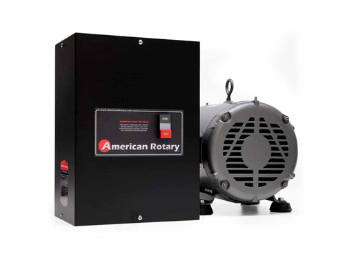
In the old days we would install a rotary phase converter. Single phase in 3 phase out. You can also do a static phase converter.
 
Victron multiplus IIs can be set up for 3 phase output and i believe still allow you to connect 1 leg to the grid/generator. They only have a few ul1741 listed currently so you would need to stack them to get the amount of power you need on each phase. Their website says you can stack 6, but I don't know if that us total or per phase. I would assume it's per phase because their configuration tool allows you to set up 4 different input power lines per phase, meaning at least 12 inverters if fully set up.
 
3-phase motor, no capacitors.

But the labels I've seen show large surge, locked rotor amps.
Here's a Dayton 7.5 HP motor

Rated voltage : 230/460 V
Rated current : 18.5/9.25 A
L. R. Amperes : 135/67.5 A


Looks to me like the rated voltage & locked rotor current is 18 kVA per phase, 54 kVA for a 3-phase source.
Rated current, 7.5 kVA or 1 kVA per HP.

Starting surge is almost twice what 3x Sunny Island can provide.
Probably SolArk could do it. If Victron can be stacked for 3-phase, that may too.

If it doesn't need full torque at start-up, I think wiring for the higher voltage would cut current and kVA in ~ half. Then switch to lower voltage configuration for operation.
 
Using multiple sol-arks you can get 3 phase output, see the diagram in the manual, if you don't have the proper 3 phase tgrid feed you won't be able to use grid power with the sol-arks. Your setup would need to be fully off-grid, with inverters and batteries to handle the full load, and peak demand. You could add a separate battery charger that will charge the batteries from the grid to get some grid power in to this system.
I realize this thread is old.

In theory, why (aside from firmware and possible PCB limitations) could 3 inverters working as a 3-phase team with a battery bank not function as a common solution to convert 2-leg grid into a 3-phase output as long as pass-through was disabled? let me get specific before you answer, I even think the device could be designed so pass through could be enabled on 2 of the units.

1. If pass through would be disabled. Inverters 1+2 would charge battery bank with AC-DC charging capability built in. Inverter 3 would not have grid input, but all 3 would function as mentioned above as if they were truly off-grid. (we are just using the built in chargers)

2. to take this 1 step further, if the 2-phase grid source was in reality 2 of 3 legs from a 3-phase distribution at the street (120deg phase) i think passthrough could work fine on the 2 grid inverters. the 3rd inverter would need to be a slave, but syncing the phases would be easy in firmware.
 
In theory, why (aside from firmware and possible PCB limitations) could 3 inverters working as a 3-phase team with a battery bank not function as a common solution to convert 2-leg grid into a 3-phase output as long as pass-through was disabled?
AIO inverter can't generate phase or freq that differs from input phase angle / freq. Doing so would require rectifying input to DC then inverting back to AC. AIO hybrid inverter hardware is incapable of rectifying grid input to DC and generating different AC phase angle on output. Essentially hybrid AIO is a grid-tie inverter internally that parallels to grid input which gets directly connected to load output.
 
AIO inverter can't generate phase or freq that differs from input phase angle / freq. Doing so would require rectifying input to DC then inverting back to AC. AIO hybrid inverter hardware is incapable of rectifying grid input to DC and generating different AC phase angle on output. Essentially hybrid AIO is a grid-tie inverter that parallel's to grid input which gets connected to load output.
I am not talking about a specific brand, I am talking about hypothetical firmware update to off the shelf single phase inverters, where 3 of them are working as a group to produce 3 phase, 2 in pass through, also rectifying thier inputs to provide the 3rd inverter DC to generate the 3rd phase that was NOT run from the street.

I am suggesting that off the shelf inverters appear 99% physically capable of what I am talking about from a hardware perspective.
 
Most inverters use same circuits and/or transformers to invert as to charge. They can't charge from grid unless they pass through grid.

I do use 3x SI configured 120/208Y, fed from 1 leg of 120/240V, to create 3-phase.
Master passes through 125V and charges battery, Slave1 and Slave2 create L2 and L3, 120V.
(Would be better if slave voltage tracked pass-through voltage.)

If you had inverters that made 120/240V high-leg delta, then you could pass through two phases. I've tried to force-fit that onto my system by various transformer schemes, e.g. 138V legs seen by inverter with their neutral not grounded, synthesize a neutral to ground. But all attempts have either not connected (while phase slips, voltages go wild relative to grid), or connects and draws a lot of power (maybe phase angles.)

I think it could be done for high-leg delta if inverter supported that.
A single inverter could generate the high leg, if synced to grid + 90 degrees.


What I've got running works for 6.7kW pass through/charging. Beyond that, draws power from battery or relies on PV.
 
Most inverters use same circuits and/or transformers to invert as to charge. They can't charge from grid unless they pass through grid.
this should have been obvious to me, i am powering on inverter 1 for the first time tomorrow and would have been surprised. now i have 12 more hours to let that sink in, thank you.

so you are already doing it, with some minor issues. thanks for sharing.
 
Back
Top