diy solar

diy solar

3000W LF 12V inverter repair

Supervstech

Administrator
Staff member
Moderator
Joined
Sep 21, 2019
Messages
11,553
Location
Belmont, NC
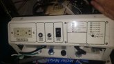
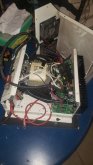
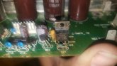
Ok, so I bought a parts inverter... a quality inverter.
Got it home, hooked up test leads to a battery, 18ga jumpers...

Powering this on, SMOKES my test leads.
How many amps should an inverter pull just powering on?

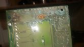
And, yes... I resistor charged the capacitors first.

I will use larger wire for my next test, but I wasnt expecting serious amps on a simple power up...
 

Attachments

  • 20200606_103744.jpg
    20200606_103744.jpg
    89.8 KB · Views: 13
  • 20200606_103734.jpg
    20200606_103734.jpg
    48.3 KB · Views: 17
  • 20200606_103627.jpg
    20200606_103627.jpg
    110.5 KB · Views: 18
I wouldn't expect that. Sure the transformer will suck up current for a brief time when the unit is turned on as it builds a magnetic field but getting the wires hot enough to smoke says you have longer term high current to me. Time to check the transistors driving the transformer but if they were shorted I'd expect you to see high current from the get-go unless the on/off switch actually breaks the DC supply instead of being a soft off type.

I can't speak for how that particular inverter behaves but I have had a 2kW LF inverter on the bench via similar wiring. When the transformer was first powered there was enough surge current to cause the wires to shift (the magnetic field the wires generated pushing them around) but no where near smoke coming off them.
 
Last edited:
The unit clicked on off on off with the small jumpers.
My guess is the xfmr needs more current than my leads can supply.
Once I have my fuses, 4gauge and quick disconnect in place, I will try again, but I'm guessing a board has damage I cant see right now.
It is a soft on/off switch, there is a power on switch and a remote switch I have to connect to 12v positive.
 
Ugh... I am taking this apart, and FRUSTRATED...
Why are all the wires the same color?
I have to lable everything to make sure it all goes back together...
 
Arrrr matey, thar she blows. That certainly explains the high current smoking the wires.
 
Well I figure replace them all... 32 biguns, a boatload of resistors, and a pair of little ones...
 

Attachments

  • 20200607_213227.jpg
    20200607_213227.jpg
    44.9 KB · Views: 6
  • 20200607_212941.jpg
    20200607_212941.jpg
    47.5 KB · Views: 6
Can you tell if there is any feedback path from the output side of the transformer or a light feedback winding? If there isn't you can probably run it without the output transformer connected or even the output transistors fitted too. With no output and driver transistors fitted power it up and check the waveforms going into the driver transistors to see if the chip is still kicking and making sense then work your way back to normalcy from there. Nothing worse that fitting a bucket of output transistors only to see them go pop because the control circuitry was toast.

That IR chip is a FET driver so probably no intermediate drive transistors before the big boys. You should be able to probe it's hi and lo side outputs to see if they make sense before putting the output transistors back in. https://html.alldatasheet.com/html-pdf/82793/IRF/IR2110/45/1/IR2110.html
 
Looks like this thing spent time underwater...
 

Attachments

  • 20200607_220128.jpg
    20200607_220128.jpg
    78 KB · Views: 7
  • 20200607_214154.jpg
    20200607_214154.jpg
    40.2 KB · Views: 7
  • 20200607_214146.jpg
    20200607_214146.jpg
    76.9 KB · Views: 6
Can you tell if there is any feedback path from the output side of the transformer or a light feedback winding? If there isn't you can probably run it without the output transformer connected or even the output transistors fitted too. With no output and driver transistors fitted power it up and check the waveforms going into the driver transistors to see if the chip is still kicking and making sense then work your way back to normalcy from there. Nothing worse that fitting a bucket of output transistors only to see them go pop because the control circuitry was toast.

That IR chip is a FET driver so probably no intermediate drive transistors before the big boys. You should be able to probe it's hi and lo side outputs to see if they make sense before putting the output transistors back in. https://html.alldatasheet.com/html-pdf/82793/IRF/IR2110/45/1/IR2110.html
Hell, I’m an electrician, not a mad scientist!

I would need detailed instructions to do this, I know very little about electronics...

The control board doesn’t have any visible damage I can see...
 
Take a look at this youtube channel. It's an audio amp repair channel but the approach he takes to repairing the output stage will be quite comparable to where you are with those dead transistors in your inverter.
 
Oh, I have desoldering and soldering skills, just no way to probe or test anything...

Can you tell from the pictures what fets I would need to order? I have butloads of resistor strips, I'm sure I have those.
 
I will clean all the crap off the boards, replace the conformal, and replace all the burned stuff and try it.
 
Why spend all the time when it could just happen again. If it looks like it was wet then who knows what else will try.
 
My sig says it all... all around lunatic...

I tinker, and having repaired something this awesome just makes me warm and fuzzy...

assuming it works.
 
Oh, I have desoldering and soldering skills, just no way to probe or test anything...

Can you tell from the pictures what fets I would need to order? I have butloads of resistor strips, I'm sure I have those.
That board looks pretty ugly, I'd be hesitant to tell you to order anything at this point. My first step would be to try to run it without the FETs in place to see if what is coming out of the IR FET driver chip is making sense, that'd require a oscilloscope.
 
That board looks pretty ugly, I'd be hesitant to tell you to order anything at this point. My first step would be to try to run it without the FETs in place to see if what is coming out of the IR FET driver chip is making sense, that'd require a oscilloscope.
And some idea how to read one I bet.
My old boss has a full set of electronic diagnostic stuff, I bet he would let me use his scope.
 
Ok, I’m thinking I will hold off trying to repair this for now...

but a customer of mine bought a house, and the sellers left him a present...

image.jpg

it is an AlphaTechnologies 3000 W UPS. I like the expansion Anderson connection... I hooked it to my 48V battery bank, but it has a service light, that translates to bad control board... and the board is NLA...

Anybody wanna try figuring out what is wrong with the board?
 
Back
Top