diy solar

diy solar

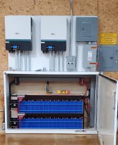
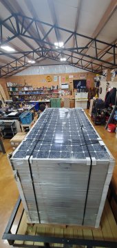
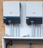
4 MPP LV6548 / 30 kW EVE 304ah LiFePO4 battery/ 14 kW PV array

Super jealous of your cabinet! Been looking everywhere for something similar thats affordable but coming up short!
I do industrial electrical work for a living. I am sad to say I bring enclosures like this to the recycling yard on a regular basis. You would do well to check out your local scrap yard. You might be surprised.
 
Very nice work.
I'm sure everyone can glean an idea or two from what you're doing. Thanks for sharing.
 
I do industrial electrical work for a living. I am sad to say I bring enclosures like this to the recycling yard on a regular basis. You would do well to check out your local scrap yard. You might be surprised.
Thanks! Good tip! I’m in a similar field (UPS Tech) but never really run across anything good like this.
 
Super jealous of your cabinet! Been looking everywhere for something similar thats affordable but coming up short!

Yeah he took the trough idea to a whole new level, and did a whole cabinet there, like a big tall trough large enough for all the batteries hehe! I like it too :geek:
 
Thanks! Good tip! I’m in a similar field (UPS Tech) but never really run across anything good like this.
This enclosure was pretty ragged when I got it. Took a little welding to reorient the door to open this way. The cabinet was originally design to stand vertically not in the horizontal position I have it in now. A little enamel paint covers a multitude of sins.
 
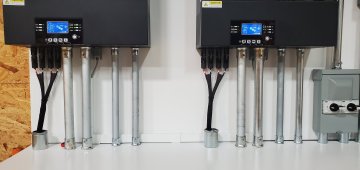
Have you decided yet how to handle the MC4 connectors?

1640727385729.png

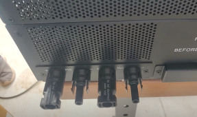
I never did like the way MPP has them coming directly out the bottom like that. I did buy a 6-ft wide trough to put under my LV6548s, and I'm gonna do conduit runs same like you.

However, I don't like the idea of using the MPP's MC4 connectors and having raw cable-runs run right into the bottom of the inverter, it just doesn't look as clean as the Sol-Ark installs for example (where all runs can be inside conduits).

Like I'd rather have all-conduit runs for cleanest, professional look (I'm an old car stereo installer guy from the 90's, I also like to do clean installs and rather go all the way, or none of the way, if I'm going to go through the trouble, it should look clean, and no raw cables hanging out).

I was thinking of either remounting the MC4s inside the box, having a single smaller diameter conduit going into the case, or removing the MC4 connectors altogether, and installing terminal blocks inside the MPP case.

Or just putting a big fat conduit that is large enough to go around all four of the MC4 connectors (not screwed on, just butted up flush against bottom of case). That would make it a lot more tricky to get the MC4 connectors apart later, working inside of a large conduit coming up from the bottom of the trough/box... Or making the fat conduit, slidable with some set screws, so it is more a cosmetic thing where you can loosen set screws on the bottom and slide it down to get the MC4 connectors apart if needed.

I am leaning towards just removing the MC4 connectors. Other idea is to soldier in longer pigtails inside the MPP case and extend the longer wires down to the trough/box below, and put PV terminal connection blocks down there where there is more room.

What did you have in mind? Or are you not going to worry about that and just connect your raw PV cable runs right to the factory connectors and not have conduit there?
 
Last edited:
Have you decided yet how to handle the MC4 connectors?

View attachment 77454

I never did like the way MPP has them coming directly out the bottom like that. I did buy a 6-ft wide trough to put under my LV6548s, and I'm gonna do conduit runs same like you.

However, I don't like the idea of using the MPP's MC4 connectors and having raw cable-runs run right into the bottom of the inverter, it just doesn't look as clean as the Sol-Ark installs for example (where all runs can be inside conduits).

Like I'd rather have all-conduit runs for cleanest, professional look (I'm an old car stereo installer guy from the 90's, I also like to do clean installs and rather go all the way, or none of the way, if I'm going to go through the trouble, it should look clean, and no raw cables hanging out).

I was thinking of either remounting the MC4s inside the box, having a single smaller diameter conduit going into the case, or removing the MC4 connectors altogether, and installing terminal blocks inside the MPP case.

Or just putting a big fat conduit that is large enough to go around all four of the MC4 connectors (not screwed on, just butted up flush against bottom of case). That would make it a lot more tricky to get the MC4 connectors apart later, working inside of a large conduit coming up from the bottom of the trough/box... Or making the fat conduit, slidable with some set screws, so it is more a cosmetic thing where you can loosen set screws on the bottom and slide it down to get the MC4 connectors apart if needed.

I am leaning towards just removing the MC4 connectors. Other idea is to soldier in longer pigtails inside the MPP case and extend the longer wires down to the trough/box below, and put PV terminal connection blocks down there where there is more room.

What did you have in mind? Or are you not going to worry about that and just connect your raw PV cable runs right to the factory connectors and not have conduit there?
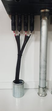
What do you think. Not loving the solution but have not com up with anything better.
 
Super jealous of your cabinet! Been looking everywhere for something similar thats affordable but coming up short!
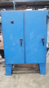
That is a Hoffman cabinet just like the one I purchased. https://diysolarforum.com/threads/house-system-battery-box-hoffman.32305/ Here is what it looks like standing up.

Hoffman cabinet standing.jpg

He took the legs off and turned it on the side. I showed the cabinet to my daughter's boyfriend and he told me he runs across them now and then, he works for a company that removes transformers in sub stations. He might get some more for me. They are heavy.
 
That is a Hoffman cabinet just like the one I purchased. https://diysolarforum.com/threads/house-system-battery-box-hoffman.32305/ Here is what it looks like standing up.

View attachment 77474

He took the legs off and turned it on the side. I showed the cabinet to my daughter's boyfriend and he told me he runs across them now and then, he works for a company that removes transformers in sub stations. He might get some more for me. They are heavy.
My enclosure looked exactly like that only with one large door.
 
Regarding your BMS compensates for balance lead resisance, which BMS is that? I went with Batrium and getting ready to start adding balance leads and wondered if it could be configured the same.
 
It is JK 24S 2A 200A BT. I have only been running my system for 2 days so I have very little to go on. So far it seems to be working perfectly.
 
What do you think. Not loving the solution but have not com up with anything better.

I guess it doesn't look too horrible, I'd hate to spend too much time worrying about something simple like this when there are other bigger fish to fry and get through the rest of the install first, supposing if you later considered to circle back on it. I guess it would give more time to think about what you would do with it, or whether to leave it.

Here's another idea which might be simple enough to do, maybe if the conduit fitting (where the PV wires come out of) had a longer conduit attached and went up a little higher, closer to the MC4 connector, and custom make a square shroud cover to screw onto the bottom of inverter (only a bit wider than the MC4 group), that is tall enough to overlap and cover up the conduit coming up?

I don't know, I might just sit on it longer and think about more. I haven't started any of my install yet, I still need to get a basic structure up first.

Yours is looking great though...
The fun of it is to worry over the details. ?
 
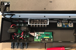
How do those PV cables land inside the unit ?
I suppose a plastic conduit like the type used for mini-split HVAC might work.
 
How do those PV cables land inside the unit ?
I suppose a plastic conduit like the type used for mini-split HVAC might work.

It looks like this:

(From random You Tube video)
1640755539275.png

(From my own LV6548s)
1640755719806.png

1640756003279.png

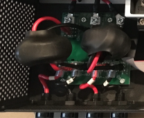
When I zoom in, as seen on the last screen cap, where the MC4 connectors have short pigtails, they look like they attach to connectors on the little board there. I have mine at the storage unit in the shipping boxes now (for now I can only review this picture I took awhile back), so it's hard to see how it attaches onto the board. They might be spade connectors or screw down connector bosses. If I remember right, I remember thinking that they had not been soldiered, and are removable.

It seems like those mini-split HVAC line covers could be one option (if you wanted to leave the MC4 connector setup intact)...

My original idea was to just use one of the existing case conduit holes to the right a bit (underneath where the AC Input wire attaches, and just have the AC input and AC outputs use the other hole under the AC output), have the PV input come in on that left conduit hole, and directly attach the PV inputs right to that board. Then I wouldn't have to cut up the MPP case (with a new hole) and possibly void the warranty, it could be easily returned back to original if warranty service was required.

In my case, I will be fully off-grid and if I have an AC input it will be only large enough wire for a generator power source... I should be able to get both AC inputs and outputs through the other hole.
 
Last edited:
Looks somewhat easy to make your own plate and put EMT couplers in it. It appears they terminated with 1/4" lugs onto a filter board.

You made a neat job using the MC4 connectors but I think that could fail any NEC inspection.
 
Back
Top