Hi guys first post as im new here.
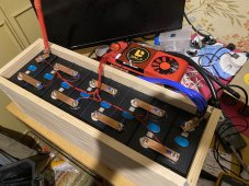
I have a 400a daly smart bms. wired up to my 8s lifepo4 280ah eve bank.
Checked the balance leads 4 times. neg then 3.6v 7.2v and so on in order so all good.
Temp probe is connected and i tried reconnecting 3 times.
Shorted b- to p- many times.
tried charging but charger will not sense bms.
Tried a power supply no difference.
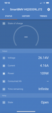
I can measure pack voltage on the positive battery poste and p- leads. 28.1v pack reads 28.3v on the battery posts.
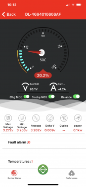
Bluetooth wont show up in the app.
if i apply a load nothing powers up.
Uart cable works but nothing shows in the software scans but says not responding.
I cant think of what to try next? Its just un responsive. ?????
I have a 400a daly smart bms. wired up to my 8s lifepo4 280ah eve bank.
Checked the balance leads 4 times. neg then 3.6v 7.2v and so on in order so all good.
Temp probe is connected and i tried reconnecting 3 times.
Shorted b- to p- many times.
tried charging but charger will not sense bms.
Tried a power supply no difference.
I can measure pack voltage on the positive battery poste and p- leads. 28.1v pack reads 28.3v on the battery posts.
Bluetooth wont show up in the app.
if i apply a load nothing powers up.
Uart cable works but nothing shows in the software scans but says not responding.
I cant think of what to try next? Its just un responsive. ?????