diy solar

diy solar

48v battery help.

shakenup5

New Member
Joined
Feb 19, 2024
Messages
5
Location
Cambridge
I have purchased two 48v 100ah batteries from China.

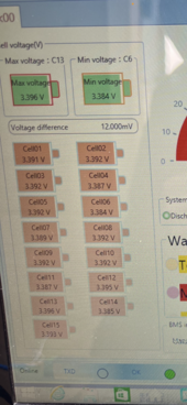
Upon arrival the batteries charged at the max rate of 3kw until 60% charged. I presume they then went in to balance mode as the rate then dropped to around 500w. This normally happens at 90% I believe.

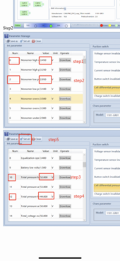
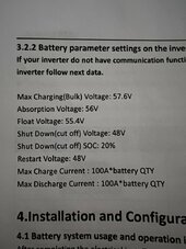
The Chinese company suggested I change the 4 values that I have attached in the image.
This fixed the charging issue at 60% and increased it to 95%!

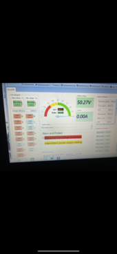
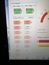
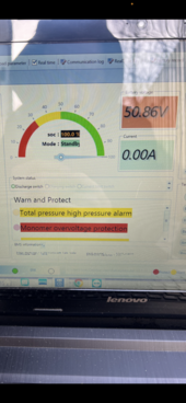
It has now led to another issue. At 100% charge the batteries display “Monomer Overvoltage protection” (I have attached images).
The inverter throws an error to preventing discharge.

Obviously changing the values has fixed one issue but caused another?
Can anyone see anything obvious that would be causing this? Should the monomer voltage be higher?

Thanks in advance!
 

Attachments

  • 84AB9DB5-8475-4ECE-8794-6DAE79DD939B.png
    84AB9DB5-8475-4ECE-8794-6DAE79DD939B.png
    231.8 KB · Views: 18
  • 2F07E2E4-C087-4413-B564-FB4C6DBD6B95.jpeg
    2F07E2E4-C087-4413-B564-FB4C6DBD6B95.jpeg
    152.4 KB · Views: 18
  • 5A3C63AC-EC8B-4929-A78B-E12B93B3884F.png
    5A3C63AC-EC8B-4929-A78B-E12B93B3884F.png
    281.5 KB · Views: 16
  • 5B3021D1-C637-43AB-B931-45B57A5B8450.jpeg
    5B3021D1-C637-43AB-B931-45B57A5B8450.jpeg
    199.6 KB · Views: 21
From the image, it appears you've got 15S battery.
The data 3.2.2 in second figure corresponds to 16S, and even then the recommended float and max. charge current values are wrong.

Setting the (monomer) Cell OVP to 3.5 instead of 3.45V should fix this problem.
At the same time, there is no way to guess what other problems you might face.
 
It is difficult to determine the true state of charge on LFP (Lithium Iron Phosphate) batteries. This is due to them having a very flat voltage across a wide range of state of charge. The voltage hardly changes between 20% and 80% SoC. The only time the voltage swings is at the extreme ends of the charge curve. If the cells are even a small amount out of balance, the highest state cell can quickly run away to a higher voltage and cause the error you are seeing.

Charging at 3,000 watts is about 60 amps of current. Most 100 amp BMS units only have about 0.1 amp of balance current. As the battery comes close to fully charged, the high cell starts to run away. The balancer will pull it's 0.1 amp load on the high cell, but 60 amps of charge current is not going to even notice that. You may need to charge the battery at a very low current and raise the voltage slowly to give the balancer time to get the cells all top balanced. Looking at your 4th picture, is it just a 15 cell battery? That is odd for a 48 volt LFP system. Most are 16S. LFP cells are 3.2 volts nominal. They are completely discharged at 2.7 volts and fully charged at 3.45 volts, but to fully absorb charge them faster, they can be pulled up to 3.65 volts safely for about an hour. For this reason, most BMS units are set to not shut down until a cell exceeds 3.65 volts.

If your battery is really just 15S as it appears to be, that gives a usable range of 40.5 volts on the low end up to 54.75 on the high side with perfectly balanced cells. But to get a solid charge without perfect balance, it is common to just charge to 3.45 volts per cell or 51.75 volts for a 15 cell battery, or 55.2 volts if it is 16 cells. Your screen shots really look like just 15 cells, but the second picture with the battery parameters are for 16 cells. I think this is your biggest problem. You need to know for sure what those batteries really are to set good charging settings. From the first picture, I am not clear what parameters you changed and what they were before you changed them.

The error you have now is one cell is going to too high of a voltage so the BMS is disconnecting the battery. That is why the inverter is throwing an error as well. The two BMS screen shots are hard to read, but those are certainly not at full charge at just 3.35 volts per cell. It's close to full charge, but no cell is hitting the upper knee and going into where it would be shutting down. 50.27 volts for the whole battery and 3.35 volts per cell works out to 15 cells. From 3.15 volts to 3.35 volts, the cells are between 20% and 80% charged. The voltage seems to change more with temperature than with state of charge.

To get the battery safely charge to near full, I would suggest trying just 10 amps of charge current with the bulk charge voltage limit set to just 51.75 volts. That should get all of the cells to 3.45 volts. Then set the absorb voltage a little lower, like 51 volts even and the float voltage should be around 50.5 volts and see how that works.

The BMS should have the single cell voltage limit set to 3.65 volts, and the total battery voltage limit set to 54.75 volts.
 
but to fully absorb charge them faster, they can be pulled up to 3.65 volts safely for about an hour.
It's not dependent on time, rather when the charging current tapers down to 0.05 C. In most cases, it happens wayy earlier than an hour.
An hour spent at 3.65V is nothing but accelerated Cell damage.
calb battery charging.png
 
It is difficult to determine the true state of charge on LFP (Lithium Iron Phosphate) batteries. This is due to them having a very flat voltage across a wide range of state of charge. The voltage hardly changes between 20% and 80% SoC. The only time the voltage swings is at the extreme ends of the charge curve. If the cells are even a small amount out of balance, the highest state cell can quickly run away to a higher voltage and cause the error you are seeing.

Charging at 3,000 watts is about 60 amps of current. Most 100 amp BMS units only have about 0.1 amp of balance current. As the battery comes close to fully charged, the high cell starts to run away. The balancer will pull it's 0.1 amp load on the high cell, but 60 amps of charge current is not going to even notice that. You may need to charge the battery at a very low current and raise the voltage slowly to give the balancer time to get the cells all top balanced. Looking at your 4th picture, is it just a 15 cell battery? That is odd for a 48 volt LFP system. Most are 16S. LFP cells are 3.2 volts nominal. They are completely discharged at 2.7 volts and fully charged at 3.45 volts, but to fully absorb charge them faster, they can be pulled up to 3.65 volts safely for about an hour. For this reason, most BMS units are set to not shut down until a cell exceeds 3.65 volts.

If your battery is really just 15S as it appears to be, that gives a usable range of 40.5 volts on the low end up to 54.75 on the high side with perfectly balanced cells. But to get a solid charge without perfect balance, it is common to just charge to 3.45 volts per cell or 51.75 volts for a 15 cell battery, or 55.2 volts if it is 16 cells. Your screen shots really look like just 15 cells, but the second picture with the battery parameters are for 16 cells. I think this is your biggest problem. You need to know for sure what those batteries really are to set good charging settings. From the first picture, I am not clear what parameters you changed and what they were before you changed them.

The error you have now is one cell is going to too high of a voltage so the BMS is disconnecting the battery. That is why the inverter is throwing an error as well. The two BMS screen shots are hard to read, but those are certainly not at full charge at just 3.35 volts per cell. It's close to full charge, but no cell is hitting the upper knee and going into where it would be shutting down. 50.27 volts for the whole battery and 3.35 volts per cell works out to 15 cells. From 3.15 volts to 3.35 volts, the cells are between 20% and 80% charged. The voltage seems to change more with temperature than with state of charge.

To get the battery safely charge to near full, I would suggest trying just 10 amps of charge current with the bulk charge voltage limit set to just 51.75 volts. That should get all of the cells to 3.45 volts. Then set the absorb voltage a little lower, like 51 volts even and the float voltage should be around 50.5 volts and see how that works.

The BMS should have the single cell voltage limit set to 3.65 volts, and the total battery voltage limit set to 54.75 volts.
Thanks for this comprehensive reply!

They have just confirmed that the batteries are 15 cell!

I will give your suggested settings a go today and see what happens.
 
These are the settings that the battery manufacture has suggested. Does that sound correct?

Parameter 1101-GR01


1. Single unit high voltage alarm 3.450 V


2.Single unit high voltage recovery 3.300 V


3. Single unit low voltage alarm 2.950 V


4.Single unit low voltage recovery 3.100 V


5.Single unit overvoltage protection 3.500 V


6.Single unit overvoltage recovery 3.300 V


7.Single unit undervoltage protection 2.900 V


8.Single Body undervoltage recovery 3.100 V


Balanced opening voltage 3.400 V


Cell low voltage charging prohibited 1.500 V


Total voltage high voltage alarm 52.00 V


Total voltage high voltage recovery 49.50 V


Total voltage low voltage alarm 44.00 V


Total voltage low voltage recovery 46.50 V


Total voltage overvoltage protection 52.50 V


Total Overvoltage recovery 49.50 V


Total voltage undervoltage protection 43.50 V


Total undervoltage recovery 46.50 V


Charging overvoltage protection 63.00 V


Charging overvoltage recovery 61.00 V


Charging high temperature alarm 50.0 ℃


Charging high temperature recovery 47.0 ℃


Charging low temperature alarm 2.0 ℃


Charging low temperature recovery 5.0 ℃


Charging over-temperature protection 55.0 ℃


Charging over-temperature recovery 50.0 ℃


Charging under-temperature protection -10.0 ℃


Charging under-temperature recovery 0.0 ℃


Discharge high temperature alarm 52.0 ℃


Discharge high temperature recovery 47.0 ℃


Discharge low temperature alarm -10.0 ℃


Discharge low temperature recovery 3.0 ℃


Over-discharge Temperature protection 55.0 ℃


Discharge over-temperature recovery 50.0 ℃


Discharge under-temperature protection -15.0 ℃


Discharge under-temperature recovery 0.0 ℃


Cell low temperature heating 0.0 ℃


Cell heating recovery 10.0 ℃


Ambient high temperature alarm 50.0 ℃


Ambient high temperature recovery 47.0 ℃


Ambient low temperature alarm 0.0 ℃


Ambient low temperature recovery 3.0 ℃


Ambient over-temperature protection 60.0 ℃


Ambient over-temperature recovery 55.0℃


Ambient under-temperature protection -10.0 ℃


Ambient under-temperature recovery 0.0 ℃


Power high temperature alarm 90.0 ℃


Power high temperature recovery 85.0 ℃


Power over-temperature protection 100.0 ℃


Power over-temperature recovery 85.0 ℃


Charging over-current alarm 100.00 A


Charging over-current recovery 95.00


A Over-discharge Current alarm - 105.00


A Discharge overcurrent recovery - 103.00


A Charging overcurrent protection 110.00 A


Discharge overcurrent protection - 110.00 A


Transient overcurrent protection - 250.00 A


Output soft start delay 2000 mS


Battery rated capacity 100.00 Ah


Remaining battery capacity 20.00 Ah


Cell failure voltage difference 0.50 V


Cell failure recovery 0.30 V


Equalization opening voltage difference 0.030 V


Equalization end voltage difference 0.020 V


Static balancing time 10


The number of battery cells in series is 15 Series


charging overcurrent delay 10 seconds


Discharging overcurrent delay 10 seconds


Transient overcurrent delay 30 mS


Overcurrent recovery delay 60 seconds


Overcurrent recovery times 5 times Charging current limit delay 5 minutes Charging activation delay 1 minute Charging activation interval 10 hours Charging activation times 10 times Working record interval 30 minutes Standby Recording interval 240 minutes, standby shutdown delay 48, remaining capacity alarm 10%, remaining capacity protection 5%, interval recharge capacity 96%, cycle cumulative capacity 80%, connection fault impedance 10.0 mΩ, compensation point 1, position 9, series compensation point 1, impedance 0.0 mΩ, compensation point 2 position 13 string compensation point 2 impedance 0.0 mΩ BitGroup0 FF BitGroup1 FF BitGroup2 FF BitGroup3 3F BitGroup4 BF BitGroup5 9B BitGroup6 AF BitGroup7 27
 
The first 8 numbers are all very conservative for a single LFP cell. I think the alarm voltage is a little early, but that certainly won't hurt anything, and it is not reducing the usable capacity if it runs absorb long enough. It is safe, but I can see you getting nuisance alarms if the cells are not perfectly balanced, but it won't hurt anything.

The same is true for the under voltage protections. Most LFP cells are safe going lower, but you only gain 5% capacity, so this is fine, it just alarms earlier than it really needs to. It's safe and it should last a good long time.

The total voltage high alarm is also very conservative. 52 / 15 cells = 3.467 per cell.
Then the total voltage protection is at 52.5 volts, Ok... But to get this high, every cell has to be into alarm or shut off already.

But then Charging overvoltage protection is way up at 63 volts!! That is way up there. Why is this different? 63 / 15 = 4.2 per cell. That is crazy high for LFP cells.

I do have a theory about this. The BMS seems to have a charge current limiter. In your first post, you said the charge power dropped to 500 watts. Most BMS units just shut off on over current or over voltage. The current would drop to zero. But this dropped to about 10 amps x 50 volts = 500 watts. That would most likely produce a voltage differential from the input terminals to the cells. That is a very good feature for when batteries are connected in parallel. If one battery is at a different state of charge, it will limit the current going between batteries. So maybe those voltages make sense. It will stay charging the cells even if the terminal voltage goes over 60 volts. But your inverter/charger and/or charge controller should be set to only charge to 52 volts.

@shvm is correct about the absorb charging. Tail current is the best way to fully charge the cells without extra stress. If your charging device supports tail current, that setting is the way to go. But if you are limiting the voltage to just 3.45 per cell, you can have it float there forever without harm. Going to 3.65 volts, the cells will absorb faster (but not with those recommended BMS settings) but it may actually take longer to hit the tail current, so a time limit should still be set. Holding the cells at 3.65 each for an hour is the longest I would recommend. Tail current may kick it off sooner. At 3.45 volts per cell, 1 hour may not be long enough to hit the tail current target.

With the recommended BMS settings, it makes it a bit tricky to set the charger settings without hitting alarms. Setting the bulk/absorb voltage to just 51 volts should prevent the BMS from hitting a disconnect, and then 48.75 volts for float looks good. Even if it hits an alarm, that is low enough for it to clear.

On the inverter side, the low voltage shut off point should be no lower than 45 volts to work well with those BMS settings. That should be high enough to keep it from hitting an alarm as long as the cells are decently matched and balanced.
 
Hi Gary,

I changed the Single unit high voltage alarm from 3.450V to 3.550V but am still getting the monomer over voltage alarm. The total battery voltage is 50.24v and the box is displaying red so I presume this is unhappy too! Can you recommend any other settings to change?
 
50.24 / 15 cells is 3.349333 volts per cell, if they were perfectly balanced. So that should be okay, but you seem to have at least one cell topping out. Can you log into the BMS when it throws the error and see what all of the cell voltages are at the time?

If it is just one cell out, that cell could be at 3.56 volts while all of the rest are at only 3.334 volts. That would be a cell voltage difference of 226 millivolts. So that is a fair bit out of balance.

Do you have easy access to the individual cell terminals? Or is this a sealed battery with only the main positive and negative coming out?

If you can get to the cell leads, you can place a load like a car headlight bulb across the high cell to bring it down. If not, you need to rely on the BMS balancer which is likely only 60 to 150 milliamps. Do you have a power supply or charger you can adjust down to just 50 volts even at under 1 amp? Under 1/4 amps would be even better. If you can do that, the internal balancer should load the high cell and slowly bring it down as the rest of the cells catch up. Eventually, you want the cells to all be at 3.33 volts with the total battery at 50 volts. It may take a few days to do it.
I can see the individual cell voltages but can’t access it as they are a sealed box.

I have attached screenshots of the voltages of each cell. The difference between cells isn’t massive!
 

Attachments

  • 15B85BCC-859E-42E4-A256-2E63B614A68F.png
    15B85BCC-859E-42E4-A256-2E63B614A68F.png
    928.9 KB · Views: 2
  • 4C6FFD69-5683-41C9-A574-59E921D26DB6.png
    4C6FFD69-5683-41C9-A574-59E921D26DB6.png
    727.7 KB · Views: 2
The 12 mv difference is not bad, and the alarm is now on the total pack voltage. When you took those images, the highest cell was only at 3.396 volts. That is well below the 3.55 volts you said you set for the over voltage protection. 50.86 volts total would be 3.391 per cell if they were all balanced. With a spread of 0.012 volts, you are right there.

All I can say at this point is try running it for a few cycles with the charger bulk/absorb voltage set down to 50.5 volts and the float down to 50.00 and se if it can run without throwing errors. Also set the low voltage cut off on the inverter to about 46.5 volts. That is still 3.1 volts per cell, so it should stay above the worst of the lower knee. 80% of the energy in LFP cells is between 3.15 and 3.4 volts per cell. With 15 cells, that is a running range between 47.25 and 51 volts. Dropping the top down to 50.5 is only costing you about 2% of th battery capacity, if it is able to stop the battery shut off. Can you double check the single cell protection values? You should have no issues going to 3.6 volts for the shut off, but still have the warning at 3.5 so it will warn you of imbalance, but not shut off. Up to 3.65 is okay for a while, we just don't want to keep them up there for a long time. Once it has done the absorb charge cycle, we want the float voltage down to under 3.4 volts per cell.
 
Back
Top