diy solar

diy solar

48V Parallel Split Phase wiring for a single grid-tied load center with a Interlock (manual transfer kit)

sv308

New Member
Joined
Jul 31, 2023
Messages
12
Location
Dallas
Hello everyone -
I have been searching around for what might be considered the best practice approach to accomplish a new solar build out.


I am looking at running 2x SP6548 in parrallel in Split Phase.
SP6548 Manual

I am installing a Leviton 42 space Load Center
LP420-BPD


Ideally I would like to use the Manual Transfer Interlock Kit to switch the load center between the Grid and my Inverter\Battery\Solar setup. This is the Main Load center for the house and needs to be able to run 120 and 240.

Configuring the the SP6548s seems to be explained in great detail - (setting 2P1 and 2P2 for the 180 phase difference) but i am just wanting to clarify a few things with how the power comes INTO the load center from the 2x intervers.
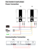
1690834487813.png


I found a few videos online of Simliar setups but i also was looking for some other opinons from the forum of my specific setup.


This video is for different inverters in parallel but obviously its the same concept
DIY Victron 120/240V Split Phase System for Beginners! No Programming Required

It has Both hots from the Inverters coming into the 2 pole breaker that would be setup with the interock kit.
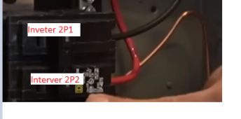
1690834706096.png


  • Is this the best way to do this of a "Off-grid" system that i want to use to power my whole house?
  • When it comes to choosing the correct size Breaker for the power coming into the loadcenter from both inverters - what would be recommended?
  • For a single unit it seems like 60amp is the size but for 2 in parrallel I was not sure from the documentation.


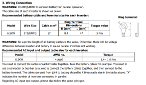
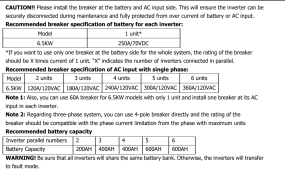
Documentation (or view the link above for the full manual):
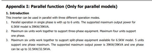
1690835018779.png

1690835034779.png
1690835052003.png


I hope my question makes sense - let me know if you need any other clarification - thanks again for your time -
 
You've mentioned switching between utility and solar/inverter but then used the term Off-Grid system so the following is what it sounds like you are looking for.
1) You wish to back-up the whole house via a main panel. The panel being powered by a 2 pole, 60A breaker. (1 hot from each inverter, neutrals tie together) That may work depending on your peak load but total power is limited by the 60A breaker. Did you perform an energy audit?
2) Its unclear how the interlock kit is to be installed. Normally the 2 hot wires are removed from the meter and routed to a separate transfer switch. The transfer switch then either sends power to the AC inputs on the inverters OR to the main panel directly. There are 2 common types of transfer switches used. Either a generator style or double throw disconnect type. In either case best practice is to locate fuses or breakers IN FRONT of the inverter and main panel. This configuration is referred to as a line side tap and the transfer switch is really more of a maintenance bypass because when the inverter is working properly it will do the switching between utility power, solar and battery depending on the way you set up Source Priority and other user menu settings.
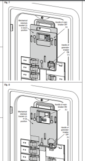
1690844819483.png

The interlock installs on top of the Main breaker and the Input breaker where the power from the backup Generator\Inverter\etc comes into the panel.

You can only turn the backup power on by turning the main breaker off so the metal panel can slide down.

I currently am ok with this being a manual process vs having some automated way of switching between power sources.
 
Yes, that would work well for a back-up only system and would be a totally manual switch over. The downside is after that much of an investment in capital and labor you would have no way of using the system to reduce utility usage on a daily basis unless you were willing to do it manually everyday. Would get annoying very fast.
 
yea i see what you mean - i guess i initially thought i would be able to leave the house on the battery full time if i had enough panels and batteries - and only switch to grid if the system was not performing correctly.

Ill investigate a switch infront of the panel that lets me still dedicate frid input to the inverter to not have to switch back and forth.

thanks.
 
Ok to follow up here
I did find a few double throw safety switches (3 pole) that could do the power source change upstream of the main panel but they were quite expensive.


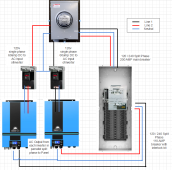
Ultimately i think a more cost effective approach with the same results would be something like this


I have power coming from the utility - it splits and goes to the panel and also to two different 120v ac disconnects (one on each phase of the 240v utility service). This would provide full time AC power to the inverters so they can charge off the grid if needed and and i can turn off the Main breaker at the panel to switch to the inverters\batteries\solar which is fed in through a 100amp breaker (along with the interlock kit per nec section 702)

My main questions are:
  • What is the best practice method of "Double Tapping" the meter that meets code requirements
    • I have seen options like Parrallel tap connectors
  • Are 2 different power sources allowed to share the same neutral bus on the main panel?
    • If not how is contsant power acheived to the inverters from the grid while the main panel is running off the inverters? Adding a disconnect to the neutral line from the grid to the panel? I suppose a 3 pole double throw safety switch in front of the panel would do this as well?
1
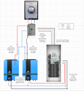
1691157830846.png

  • Would adding a new sub panel before everything make more sense? That way it would feed both interveters from 2 different 60 amp circuits and feed the main panel with a 200 amp breaker
    • The question about the shared neutral bus would still apply here as well
2
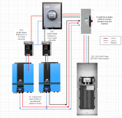
1691159677880.png


  • Another option with the 3 poledouble throw safety switch
    • This does stop the neutral from being shared but i still need to split power from the meter - so maybe a option with sub panel after the grid and the double throw makes the most sense?
3
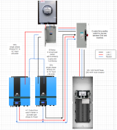
1691161709491.png

  • With the double throw and the sub panel directly after the meter.
4
1691162070608.png
Thanks
 
Last edited:
I like option #2, but I would only use one 60A 240V breaker in the first small panel. One leg going to each inverter. (keep the 200A)

I'd then run one neutral from the first panel to Inverter 1 and one neutral from the first panel to Inverter 2. Bond neutral and earth ground in the first panel as well.

You should also only need one 60A 240V breaker in the larger second panel for the inverters to connect into.

I'd then run one neutral from Inverter 1 to the second panel and one neutral from Inverter 2 to second panel. Keep neutral and earth ground separated in this panel.

Add in all of your load breakers and you should be good to go.
Ok great thanks for the input - yea in regards to the breakers for the ac input for the inverters
their documentation stated either both running through a single 120amp or individual breakers at 60A each

1691168014696.png
 
I like option #2, but I would only use one 60A 240V breaker in the first small panel. One leg going to each inverter. (keep the 200A)

I'd then run one neutral from the first panel to Inverter 1 and one neutral from the first panel to Inverter 2. Bond neutral and earth ground in the first panel as well.

You should also only need one 60A 240V breaker in the larger second panel for the inverters to connect into.

I'd then run one neutral from Inverter 1 to the second panel and one neutral from Inverter 2 to second panel. Keep neutral and earth ground separated in this panel.

Add in all of your load breakers and you should be good to go.
In regards to the Neutral from the sub panel to the main panel - are you saying that would not be needed?
And that when running on grid power with the inverters 60amp turned off at the sub panel we should be able to use the neutral from that side?
 
Back
Top