diy solar

diy solar

48v system check my work please?

LostGeographer

New Member
Joined
Jan 16, 2022
Messages
17
Hey all!

TLDR: Can you please check my work as I go? (Edit - This is for an off grid home solar system)

Background: I have a history of making weird niche mistakes no matter how many books I read or videos I watch no matter the subject. I fried my first self built PC at 16 by not using the round insulators on the motherboard mounting screws and i had two people check my work before turning it on, i have about 20 more stories like that. I know circuit boards to a point but I've never done anything of this scale and have been putting it off for months for fear of blowing my system. I'd really appreciate it if you could check my work as I go before I put any current to anything.

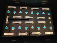
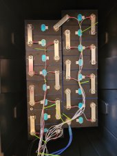
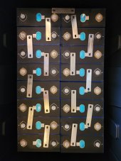
First question: Are these bus bars correct for 3.2v cells in series to make my 48v battery?

Thanks for looking!
 

Attachments

  • 20230411_112303.jpg
    20230411_112303.jpg
    128.9 KB · Views: 61
Last edited:
Yes, those are correct. However, the crossover bus bar is too long if you keep the cells in that pack. The two columns of cells will have to be moved away from each other to allow that crossover bus bar to fit.

You're going to need to put all the cells into a compression fixture, so that right there will necessitate moving the two columns apart.
 
Your topmost/horizontal bus bar is too long. You could get a shorter one, or drill a hole in the one you have so it lines up with the battery posts.
The vertical bus bars are on the wrong side of the batteries. For instance, the top two batteries show them next to the inside terminals, but they should be installed on the outside terminals. All of the remaining bus bars need to be reversed as well.
I see one of your bars has scrapes the length of it. You are right to have that facing up. If there are more like that, flip them over. You want the smoothest side contacting the batteries.
 
Yes, those are correct. However, the crossover bus bar is too long if you keep the cells in that pack. The two columns of cells will have to be moved away from each other to allow that crossover bus bar to fit.

You're going to need to put all the cells into a compression fixture, so that right there will necessitate moving the two columns apart.
I wrapped 4 each with capacitance tape or whatever the light orange brown clear tape the guy in all the videos recommends. Do I need to wrap them further?

Edit - That probably sounded like a bunch of gibberish sorry, I hate typing on my phone. I used the tape recommended in this video
Kapton tape, sorry KAPTON tape, I'll get this right so help me lol.
 
Last edited:
Your topmost/horizontal bus bar is too long. You could get a shorter one, or drill a hole in the one you have so it lines up with the battery posts.
The vertical bus bars are on the wrong side of the batteries. For instance, the top two batteries show them next to the inside terminals, but they should be installed on the outside terminals. All of the remaining bus bars need to be reversed as well.
I see one of your bars has scrapes the length of it. You are right to have that facing up. If there are more like that, flip them over. You want the smoothest side contacting the batteries.
I had them reversed at first but that put the negative and positive lines out to the inverter right next to each other on the two inside posts which made me nervous.
 
I wrapped 4 each with capacitance tape or whatever the light orange brown clear tape the guy in all the videos recommends. Do I need to wrap them further?

For a stack of eight cells, I don't think that is sufficient. If this is for a mobile environment I would never use tape. Even for a static environment, I would not use tape.
 
If you start at the bottom of the left hand eight cells and you fit your bus bars from negative to positive, the top cell negative will need to connect to the right hand side top positive. Then continue down the RHS negative to positive with the bars and you will be left with an open negative, so that short little bar at the top needs to disapear.
 
If you start at the bottom of the left hand eight cells and you fit your bus bars from negative to positive, the top cell negative will need to connect to the right hand side top positive. Then continue down the RHS negative to positive with the bars and you will be left with an open negative, so that short little bar at the top needs to disapear.
I'm sorry I must not be understanding you correctly. This is a 48v 16s battery, would there not have to be a bus bar bridging the two stacks of 8 to make it a 16s battery? Otherwise I have two 24v 8s batteries no?

I went ahead and took a picture since your the second or third person to say this but isn't it a bit dangerous to put those eyelits that close together on your negative to bms and positive to the inverter? I mean I figure it'd be super easy to short just using a socket to tighten the nuts.
 

Attachments

  • 20230413_131052.jpg
    20230413_131052.jpg
    179.9 KB · Views: 21
The way you have the bus bars setup now is correct. Yes, the opposing Pos and Neg are close to each other. Just go slow, think ahead, and be careful when working on them so you don't short them together. The whole top of that battery is a mine field for things that conduct, not just those 2 output terminals. I'd recommend you cover all parts of the battery you're not actively working on, and wear glasses when working on it.
 
Thinking out loud, if the goal is to have the terminals that you connect cable to, to be far apart then the crossover bus bar (from one column to the next) would have a much longer distance to span. You would probably not even use a bus bar for that connection, it would have to be a large gauge cable.

I would rather have two terminals close together than have to use a cable to span the two columns.

The alternative to that issue is to put all 16 cells in a single column. The terminals that you connect the cables to would be VERY far apart.
 
Why not cut some 1/4" board to fit between thos two banks of 8 cells about 2" deeper than the cells so that you then have 2" of insulating material between those connections.
 
Why not cut some 1/4" board to fit between thos two banks of 8 cells about 2" deeper than the cells so that you then have 2" of insulating material between those connections.

Not a bad idea. Or, take that 1/4" board and have it rise 2" above the top of the cells and you have a nice "firewall" between the two connection terminals.
 
Hey Guys,

So thanks for all the help so far, I went ahead and pushed one battery slightly forward compared to the other, so they are offset just enough they can still sit flush while the one that crosses the two rows still bridges the gap but without any weight on it, it also gave me a little better feeling not having those terminals that close.

My question now is this. I have a steel pipe buried about 5 feet and a few more attached to it that I use as my cell booster tower (25 feet above ground 5 below). Is it safe to put my grounding rod within 10 feet of this or do I need to move my tower somehow?
 
Hey guys, I tried putting the nuts on and when I got to the last one it started sparking on that nut. Does that mean I did something wrong? Is it ruined?
 

Attachments

  • 20230419_100252.jpg
    20230419_100252.jpg
    134 KB · Views: 27
Where does that black double-8 gauge wire go? That should be going to your positive output terminal, not the BMS.
Do you have a load connected to your battery?
Your balance leads are not in ideal locations, the bus bars have resistance and that is going to mess with proper sensing.
 
Disconnect the black wire from the positive terminal. You may have fried your BMS. The black wire goes to your negative load. The positive battery terminal goes to your positive load as @sollap mentioned.
 
Ok this figures, I looked at it for days trying to make sure it looked like the diagram and I still missed that. Fuck me. Anyway, how do I tell if I fried my BMS? As to bms connections, that's how they showed it in the guide, should they be under the bus bars?

edit - no, no load connected, just the bms in a fucking loop like a jackass
 
As to bms connections, that's how they showed it in the guide, should they be under the bus bars?

Absolutely not under the bus bars. Almost everyone puts the balance lead on the stud and on top of the bus bar. You can drill a hole in the bus bar and put a screw into that to hold the balance lead, but putting the balance lead on the cell stud is easier.
 
With any luck, the BMS could have seen that as an overload or direct short across the output terminals and just shut down. Do you have an app to connect to the BMS? A load to test with?
The balance leads should be on top of the bars as you have them, but would be better at each battery positive post. See below.

1681923822620.png
 
Finally something I saw too. I've been staring at it for days. I even downloaded the pdf to make sure it was 16 in a line and not two stacks of 8 sideways. But that's how the guide insisted.

As to an app I do believe so as I can see it Bluetooth broadcasting. I'll be back if it's not dead.

Thanks for the help.20230419_153104.jpg
 
Back
Top