The Growatts can be paralleled in multiples including 3 phase.It is phase sensitive in the sense that each leg is 180 degrees out of phase with the other.
That is the tricky part about using two inverters to create 240 volts. It is important to know how to make them work properly. Do they create true split phase when sycronised? Or do you just get two 120 volt inputs and no 240? I don't know because my inverter is 240 volt split phase.
You are using an out of date browser. It may not display this or other websites correctly.
You should upgrade or use an alternative browser.
You should upgrade or use an alternative browser.
4S or 8S BMS?
- Thread starter RobRoy
- Start date
Ampster
Renewable Energy Hobbyist
Then you will presumably have split phase.The Growatts can be paralleled in multiples
And presumably synchronized.Then you will presumably have split phase.
Ampster
Renewable Energy Hobbyist
Yes, but as @Rocketman pointed out using a 30 Amp 120 volt dogbone can create issues if the right isolation isn't there.And presumably synchronized
Last edited:
Ampster
Renewable Energy Hobbyist
I meant reply to Elton's earlier comment about using a dogbone. I have a grid tied hybrid and have no experience with RVs but I remember reading about the 30 Amp 120 volt dogbones and why you cant run a 240 volt A/C when using a dogbone.Are you 240v for an RV?
FilterGuy
Solar Engineering Consultant - EG4 and Consumers
Yes, the dog bone jumpers the 2 hot circuits. Initially I was going to run a smaller system with a4000w/30a to my 50a RV. I wanted to reuse a 30' length of 8AWG 50a RV connection cable and was using a 30a-50a dog bone. But I increased to run the full 50a/6000wI meant reply to Elton's earlier comment about using a dogbone. I have a grid tied hybrid and have no experience with RVs but I remember reading about the 30 Amp 120 volt dogbones and why you cant run a 240 volt A/C when using a dogbone.
FilterGuy
Solar Engineering Consultant - EG4 and Consumers
BTW: There should be only one bond between neutral and ground. If you are plugged into a power monument at a campsite, it will have the N-G bond and there should not be another one on the circuit. When you are not plugged into shore power, a N-G bond needs to be added. Some inverters do this automagicly. If yours does not, you need to figure out how to accomplish it.
FilterGuy
Solar Engineering Consultant - EG4 and Consumers
I have lost track of who has what on this thread. What make/model inverter do you have?I will check my inverter.
Ampster
Renewable Energy Hobbyist
I am not familiar with the requirements of RVs. I was glad @FilterGuy was able to answer your question. He also has better graphics than I.Any suggestions Ampster?
Last edited:
FilterGuy
Solar Engineering Consultant - EG4 and Consumers
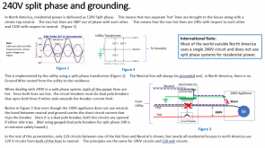
For normal on-grid house wiring in the US, the main breaker panel is the only place on premise you should find the N-G bond and the NEC calls it a 'Main Bonding Jumper'. However, in an RV using an inverter and shore power it is usually not in the main AC breaker panel because it has to be dynamically established when not on shore power.Thank you Filterguy. Good info, knew I read it somewhere and I think it mentioned the breaker panel was the best spot. I will check my inverter.
BTW: A lot of this is covered in these two resources:

Grounding Made simpler - Part 1: AC/houshold grounding
To get the paper, click on the orange button at the top of the screen. The subject of grounding is a complex, multifaceted subject, that is often treated as an after-thought but needs to be considered from the beginning of the design and build...

Grounding Made simpler - Part 4: Mobile systems.
To get the paper, click on the orange button at the top of the screen. The subject of grounding is a complex, multifaceted subject, that is often treated as an after-thought but needs to be considered from the beginning of the design and build...
Thanks for looking at this FilterguyI have lost track of who has what on this thread. What make/model inverter do you have?
FilterGuy
Solar Engineering Consultant - EG4 and Consumers
I have had a hard time getting info on what GroWatt does with the G-N bond.Thanks for looking at this Filterguy
FilterGuy
Solar Engineering Consultant - EG4 and Consumers
You may want to follow this thread:

 diysolarforum.com
We are trying to figure out what Growatt does on that thread as well.
From that thread, it does look like the Growatt is inserting a N-G bond, but I can't tell if it is permanent or dynamic.

Growatt 3kw wiring question
I have installed a 6 circuit Reliance Controls generator sub panel transfer switch 30 amp 120v. It has 6 circuit breakers in it that I have wired to 6 circuits in my main panel. Three of the circuits in my main panel that I connected are GFI breakers. The generator panel is fed with the...
We are trying to figure out what Growatt does on that thread as well.
From that thread, it does look like the Growatt is inserting a N-G bond, but I can't tell if it is permanent or dynamic.
MrM1
I'm Here, But I'm Not All There
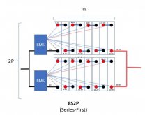
I am in a similar boat as the OP. I am trying to create a DIY 24v pack, but I need 200amp discharge. I have a Schneider SW 4024 4000w inverter and Midnite Solar Classic 150 CC.
I see the OverKill Solar BMS for 8s is only rated for 100amp. But @FilterGuy are you saying in a 8s2p with 2 100amp BMS I would be able to run 200amp discharges?

But wouldn't that create an issue IF say one BMS shut down one 8s string, but the other remained active? As long as my loads did not exceed the 100amp limit of the existing active BMS I would be OK for discharge ... but it seems that with one string active and one string off, would the two series strings be getting way out of balance?
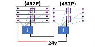
What if I was to build two 4s2p batteries for 12v, each with a 100amp 4s BMS, and then connected both of them in series for 24v. Would that put me back at a total of Only 100amp discharge? Seems that the benefit of that would be if one BMS killed one battery, that it would shut the whole 24v system stopping both charge and discharge to the entire battery bank. But would this even work? Problems / Limitations?

I just cannot find what appears to be a reliable 24v 200amp BMS that is drop in, straight forward to install, with monitoring and Hi/Low Temp cut off.
I see the OverKill Solar BMS for 8s is only rated for 100amp. But @FilterGuy are you saying in a 8s2p with 2 100amp BMS I would be able to run 200amp discharges?

But wouldn't that create an issue IF say one BMS shut down one 8s string, but the other remained active? As long as my loads did not exceed the 100amp limit of the existing active BMS I would be OK for discharge ... but it seems that with one string active and one string off, would the two series strings be getting way out of balance?
What if I was to build two 4s2p batteries for 12v, each with a 100amp 4s BMS, and then connected both of them in series for 24v. Would that put me back at a total of Only 100amp discharge? Seems that the benefit of that would be if one BMS killed one battery, that it would shut the whole 24v system stopping both charge and discharge to the entire battery bank. But would this even work? Problems / Limitations?

I just cannot find what appears to be a reliable 24v 200amp BMS that is drop in, straight forward to install, with monitoring and Hi/Low Temp cut off.
Last edited:
FilterGuy
Solar Engineering Consultant - EG4 and Consumers
Yes. That is possible. However, like you point out there are failure modes and corner cases that need to be understood. People talk about doing series first for 'redundancy' but you have to carefully think it through to know what you are getting.But @FilterGuy are you saying in a 8s2p with 2 100amp BMS I would be able to run 200amp discharges?
There are several questions to ask yourself:
- If one fails, how will I know it failed? This is important to know if you are counting on redundancy to keep you going.
- If one fails, what will happen to the other one.
There are a few scenarios here:
- If the load is less than what the remaining BMS can handle, everything keeps running
- If the load is way over the limits of the remaining BMS, it will shut down with an over-current. At that point, to take advantage of the redundancy, you would have to shed enough load to get under the BMS limit
- Perhaps the worst case scenario is that the load is right at the BMS max. At that point you are stress testing the remaining BMS. - If one fails, will the remaining one handle the charge current? (The same 3 scenarios apply here as on the load)
Yes they would, but that does not feel like a big issue for parallel batteries. When the bad BMS is fixed, and you start charging, the further discharged one will get charged. You take a chance that the lesser Discharged BMS will hit it's over-voltage disconnect, but after a couple cycles it should balance back out.but it seems that with one string active and one string off, would the two series strings be getting way out of balance?
That would limit you to the 100A limitation of the BMS. Also, there is no redundancy (if that is an important thing for you)What if I was to build two 4s2p batteries for 12v, each with a 100amp 4s BMS, and then connected both of them in series for 24v. Would that put me back at a total of Only 100amp discharge? Seems that the benefit of that would be if one BMS killed one battery, that it would shut the whole 24v system stopping both charge and discharge to the entire battery bank. But would this even work? Problems / Limitations?
Ampster
Renewable Energy Hobbyist
The best way to reduce current is to run at higher voltage. 4000 Watts at 24 volts is 167 Amps versus 333 Amps at 12 volts. What is your actual load going to be? Is it likely to be 4000 Watts?
Similar threads
- Replies
- 0
- Views
- 144
- Replies
- 1
- Views
- 211
- Replies
- 24
- Views
- 1K


