regoe002
New Member
Hey all,
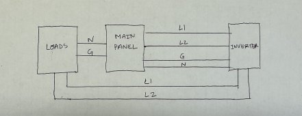
I am planning the installation of my system and have a question about Neutral and Ground connections. This will be a "grid assisted" install. Because my 6000EX-48HV inverter will be installed approximately 50ft away from my main panel I would like to connect everything as the attached diagram. I will be installing the critical loads panel next to my main panel, for ease of moving circuits. Is it ok to feed the critical loads panel N and G wires directly from the main panel and NOT from the AC OUT of the 6000EX-48HV? Would this cause an issue with N and G (bond) if utility power is lost at the main panel (and inverter)? My understanding is the inverter always passes thru the neutral, but im confused on whether it creates an internal NG bond when it senses grid down.
I would like to avoid running extra 50ft+ each N and G wire from the inverter to the critical panel if possible.
Current N/G bond is of course in the Main Panel.


