You are using an out of date browser. It may not display this or other websites correctly.
You should upgrade or use an alternative browser.
You should upgrade or use an alternative browser.
6500ex "AC" ground wire awg?
- Thread starter jfharper
- Start date
timselectric
If I can do it, you can do it.
- Joined
- Feb 5, 2022
- Messages
- 19,099
?
Same size as L1 and L2.thinking about what AWG the neutral needs to be, if considering a 240 load,
Noyou go with a much smaller AWG neutral than one would think.
The neutral must be sized for the most current it could possibly see.
Which is the same as either L1 or L2.
Once you establish your grounding system (via the N/G bond). Everything connected to the grounding system is at 0v potential to the grounding system. Multiple connections to the earth are a problem for equipment. Because of the gradient pulse created by a nearby lightning strike.So this got me thinking about grounds and grounding rods/grounding potentials. I've heard it mentioned a debate about differences in potentials occurring in the earth at diff areas. So if it's recommended to run a rod at subs in separated buildings, and for ground mount arrays, how does the entire system know what reference potential to use. Is it an average of the potentials from all rods in the earth...or does it have to do with the G/N bond location...because it is closest to the rod at the Main Panel, this Main Panel Rod sets 0v reference, and all the other rods are more like relief valves but because of their distance from G/N bond/Main Panel Rod, they don't affect the authoritative 0v reference...just curious about that.
Which is why I always recommend against them.
Current carrying conductor. When I was reading about derating for more than 3 in a raceway, someone mentioned that a neutral could not be a ccc in certain cases…still figuring that out.? CCC
timselectric
If I can do it, you can do it.
- Joined
- Feb 5, 2022
- Messages
- 19,099
YesI think I need a second #4 white leading back to the main from where the inverters are to cover the 60a circuit introduced by inv3&4.
#3 and #4 should be done just like #1 and #2.
timselectric
If I can do it, you can do it.
- Joined
- Feb 5, 2022
- Messages
- 19,099
Neutral is always a current carrying conductor.Current carrying conductor. When I was reading about derating for more than 3 in a raceway, someone mentioned that a neutral could not be a ccc in certain cases…still figuring that out.
Ground is not.
I just realized I might have a problem with 120v loads when in grid bypass over 200 feet (100ft to inv then 100ft back to load), I can only pull 30a under 3% Voltage Drop. I would either have to drop all my #4 100 foot runs to #1 to get back under 3% or just limit 120v loads during grid bypass which isn't too often...I think I'll opt for the later. We are looking to expand the battery bank maybe end of year next year if need be.
timselectric
If I can do it, you can do it.
- Joined
- Feb 5, 2022
- Messages
- 19,099
You are definitely making it super complicated. By putting all of your equipment so far away from your service.
Yeah...there are challenges/extra costs we have considered with putting it up by the service...I'd like to think this through before deciding how to proceed. We currently feel the best about keeping the equipment at the shop. Unless the complications exceed the alternative.You are definitely making it super complicated. By putting all of your equipment so far away from your service.
timselectric
If I can do it, you can do it.
- Joined
- Feb 5, 2022
- Messages
- 19,099
Balancing is good for the inverter. Doesn't change the conductor size.120v loads cancel on the neutral...maybe I could balance them to lessen the restriction.
Can you have a 100a double pole breaker, from the main panel, run through a 3 port polaris connector (for each leg) splitting to backfeeding one panel through a 40a double pole breaker, and a second panel backfeeding through a 40a breaker or higher breaker up to what the panel's bus bars can handle?
Additionally, let's say there is 2 AWG off the 100a into the polaris, then 8 awg from one port feeding the 40a breaker, and say 4 awg off the other port feeding the second panel lets say with a 60a breaker?
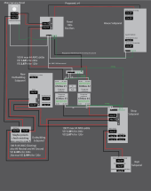
Here's where I'm at...trying to figure out the panel called "outbuilding panel." I ditched the AC-IN because I would have it turned off until needed, just like the generator lockouts, but now I don't have the 200ft 120v VD restriction.

Last edited:
timselectric
If I can do it, you can do it.
- Joined
- Feb 5, 2022
- Messages
- 19,099
YesCan you have a 100a double pole breaker, from the main panel, run through a 3 port polaris connector (for each leg) splitting to backfeeding one panel through a 40a double pole breaker, and a second panel backfeeding through a 40a breaker or higher breaker up to what the panel's bus bars can handle?
Additionally, let's say there is 2 AWG off the 100a into the polaris, then 8 awg from one port feeding the 40a breaker, and say 4 awg off the other port feeding the second panel lets say with a 60a breaker?
As long as all the conductors are sized properly for their breakers. And the secondary taps (outputs from the Polaris) are no longer than 10'.
Also the secondary taps can not be smaller than 10% of the primary feeder. But you're well above that.
One of my outputs is 100ft, I guess it won't work.And the secondary taps (outputs from the Polaris) are no longer than 10'.
timselectric
If I can do it, you can do it.
- Joined
- Feb 5, 2022
- Messages
- 19,099
You would have to add a breaker within 10' of the tap.One of my outputs is 100ft, I guess it won't work.
A small two circuit panel would suffice.
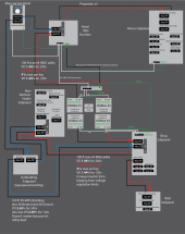
Here is v5. I'm a little stuck on some of the 120v loads. Someone mentioned to me I should keep voltage drop at 2% or less for inverter to load runs to avoid inverter tripping on over voltage regulation (I think that's what it's called). 240v loads are under 2%, but I estimated some 120v loads on some panels which probably would not be occurring at the same time and tried to balance them on each side of the panel bus bars (L1 or L2). However, there may be a chance I go over the 2% for some 120v loads as I cannot reduce the 60a breaker (to say 40a) to account for this, because I need 60a for the 240v loads AND 120v...60a is already pretty limiting? In this case, the voltage drop could go to 2.87% for the case the 120v goes above 41amps to 60amps. Do you if this will trip a 6500ex inverter?


timselectric
If I can do it, you can do it.
- Joined
- Feb 5, 2022
- Messages
- 19,099
I'm not sure why they would say 2%. The industry standard is 3%.
But even at 5% there's no problem.
My design goal is always 3%.
But even at 5% there's no problem.
My design goal is always 3%.
That’s good…it was jamming me up. Here is the post in case you’d like to review.I'm not sure why they would say 2%. The industry standard is 3%.
But even at 5% there's no problem.
My design goal is always 3%.
Post in thread 'Grid wire ampacity calc. dist. to 6500ex's, 1 way or 2?'
https://diysolarforum.com/threads/g...-dist-to-6500exs-1-way-or-2.69725/post-881765
timselectric
If I can do it, you can do it.
- Joined
- Feb 5, 2022
- Messages
- 19,099
I wouldn't be too concerned. The utility grid is only regulating to +/- 5%.That’s good…it was jamming me up. Here is the post in case you’d like to review.
Post in thread 'Grid wire ampacity calc. dist. to 6500ex's, 1 way or 2?'
https://diysolarforum.com/threads/g...-dist-to-6500exs-1-way-or-2.69725/post-881765
You have no control over that. And the inverter has no problem dealing with it.
Similar threads
- Replies
- 31
- Views
- 800
- Replies
- 20
- Views
- 646
- Replies
- 7
- Views
- 387


