diy solar

diy solar

6500ex "AC" ground wire awg?

jfharper

New Member
Joined
Jul 23, 2021
Messages
174
Many posts discuss the grounding of the array/pv mount, but I'm wondering about the necessary awg for the inverter ac ground. I know only one is necessary per inverter, and NEC Table 250.122 mentions 10 awg for 60 amps. Since the inverter can only do 54 amp, 10 awg should be enough for the ground on the AC either IN or OUT...right? I'm wondering why I'm seeing so many people run 4 awg for their AC ground? I can understand calculating for long distance and possibly upping the awg for that, but not quite getting 4 awg.

So this plans for fault for that inverter to say a connected breaker subpanel. So from that sub, what would be a good awg for running back to the main panel. Would you plan for two possible faults on two inverters which could go to 104 amps, so 8 awg for 100 amp fault or 6 awg for 200 amp fault? Or are we supposed to plan for a fault during an inrush current event, so 150% or 200% inverter capacity?

Then what if you ran 4 inverters, each of 2 connecting to a different sub, both subs wired to a ground bus in a combiner box back to the main...how many faults would you plan for to figure the ground awg from the bus to main?

I'm basically trying to figure the cost of the ground awg. Thank you.
 
@timselectric. quick code question.

Referring to the OP, he asked about 4 inverters serving 2 subpanels. This can be reduced down to 2 inverters supplying a single subpanel.
If each of the 2 inverters is protected by its own 60A breaker you would simply include 2 x 10 AWG conductors along with the Hot and Neutral wires (assuming its a 6500W, 120V) and land them on the respective inverter ground lug and continue on to the subpanel where both grounds would terminate on the ground bus.
However, could you run a single 6 AWG, daisy chain it through both inverters and then to the subpanel bus?
Alternatively land the 6AWG in the subpanel and use 2 separate 10 AWG between the subpanel and back to the inverters?
Multiple circuits can share a single EGC. And it is sized for the largest circuit.
60a is the largest. So, a single #10 EGC will cover all. (If they are traveling together)
 
Thanks for the reply. Somewhat of an unexpected answer. I would have assumed worst case scenario where both circuits developed a short circuit at the same time so would require an upsize of the EGC.
 
Thanks for the reply. Somewhat of an unexpected answer. I would have assumed worst case scenario where both circuits developed a short circuit at the same time so would require an upsize of the EGC.
Available fault current doesn't change with multiple circuits.
It only changes when the largest size circuit changes.
It's very unlikely that more than one fault occurs in the same split second.
But a small wire can carry a lot of current. If it's only required to do it for a second. Which is why EGC is always much smaller than circuit conductors.
 
OK, so different question all together.

If your running 120/240 on 2 inverters, and calculated your 240 amps load to be say 40 amps MAX over 100ft, which would require 8awg at 1.84% VD,. BUT, your 120v load you calculate to only be 10 amps MAX being pulled from a single inverter (say inverter #1) requiring 4awg, 100ft, at 2.39% VD.

Could you run ONE 8 awg hot on inverter #2, ONE 4 awg hot on inverter #1, a #10 awg for the ground at 60amps breaker...now the neutral...would you account for software glitch and both inverters would be running 120 in same direction, so 40+10 on leg1 (inverter1) and 40 on leg 2 (inverter 2), so 4 awg WHITE for inverter1 and 8 awg WHITE for inverter2 again over 100ft...thats IF both inverters glitched...in a perfect world, 240v would cancel, and only 10 amps would need to be accounted for on inverter1 thru the WHITE...is this correct? I'm sure it's bad practice, because someone down the road would not know that and could add a breaker to a bus undersized, etc. but I was just curious about it. Just trying make my understanding a little more concrete to make my design decisions.
 
Is 40a the breaker size?
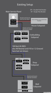
40a breaker at the house thru #8 240v which used to feed the shop subpanel. Shop subpanel has 2x20a SP and 2x15a SP and a 40a DP to the well subpanel which has DP 15a for submersible (240) and DP 15a for the booster (240), and one 20a 120 for an outlet/garden light/fountain motor, sub (5amps measure each leg) and booster (8amp measured each leg).

I'm going to repurpose the #8 for the ground wire mentioned above, and run #4 as you mentioned to the house for the house circuit, and an extra #4 to the kitchen for the Fridge/range/toaster/microwave/dishwasher/coffeemaker. I'm still calculating it all out.

I currently have 2 6500ex running with 6 Lifepower4 batts preliminarily at the shop which took over the shop subpanel, feed by #4 each...the well pumps have never started up so fast and run well, my table saw/chop saw/thickness planer/air compressor at the shop have never started and run so strong.
 
Two neutrals right...one for each inverter? Just confirming. Or 1 upsized neutral...which is more expensive...I think I would need 1/0. for 100amps at 100ft.
One neutral.
It's shared between the two lines.
I'm going to repurpose the #8 for the ground wire mentioned above, and run #4 as you mentioned to the house for the house circuit, and an extra #4 to the kitchen for the Fridge/range/toaster/microwave/dishwasher/coffeemaker. I'm still calculating it all out.
I'm having trouble following this.
The #4's should be going to a panel.
Maybe make a sketch of what you are doing. And it will make sense to me.
 
OK, this is what's existing...it's simplified at the moment.
Existing.png


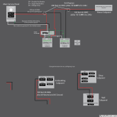
Starting sketch of proposed, I'm getting a little stuck in my thinking, is why it's incomplete at the moment:

Question #1: Regarding the neutral from Main to Panel 1. I would think #4.

I didn't draw a neutral for AC-OUT yet, from inverters to house subpanel. I would think have another panel (#2) where two short #4 whites would go into a bus bar, and then a SINGLE white going out 100 feet to the house panel, possibly #4?

However, I read a post here that discussed IF the two inverters running split phase glitched, and instead of being 180 degrees off, were not anymore. Instead of L1 - L2 (cancelling out) on the neutral for 240 loads, you could get L1 + L2 on the neutral. The 240v loads would brown out, but that neutral could see 54+54 amp = 108 amps.

So to be safe a 1/0 neutral would cover 100 amps over 100 feet which I think would be close enough (or run 2x#4). That's where that 100 amps came from I mentioned above where you asked about. This might be total overkill, but what if the glitch happened...we don't need to account for that happening when 240 is coming from the grid because it's unlikely to happen, anyway, I thought I'd mention it because it was an interesting read.

Additional this event could affect the neutral from Main to Panel 1 AND from the two inverters to say a Panel 2 I'll add in the drawing (probably having a DP 60a breaker for each inverter) then outputting to the House Panel.


Proposed.png
 
Question #1: Regarding the neutral from Main to Panel 1. I would think #4.
Correct
I didn't draw a neutral for AC-OUT yet, from inverters to house subpanel. I would think have another panel (#2) where two short #4 whites would go into a bus bar, and then a SINGLE white going out 100 feet to the house panel, possibly #4?
Sounds good
However, I read a post here that discussed IF the two inverters running split phase glitched, and instead of being 180 degrees off, were not anymore. Instead of L1 - L2 (cancelling out) on the neutral for 240 loads, you could get L1 + L2 on the neutral. The 240v loads would brown out, but that neutral could see 54+54 amp = 108 amps.
This is misinformation.
The two inverters are never 180deg off. Split-phase is single phase with a center tap.
The two inverters are wired in series for Split-phase. Or parallel for 120v only.
A glitch can't rewire the inverters.
If a glitch did manage to knock them out of sync. And for some weird reason they didn't shut down. (They would)
You would lose the 240v capability. But since the two inverters would not be in sync. The 120v neutral wouldn't be carrying the combined load simultaneously.
So to be safe a 1/0 neutral would cover 100 amps over 100 feet which I think would be close enough (or run 2x#4). That's where that 100 amps came from I mentioned above where you asked about. This might be total overkill, but what if the glitch happened...we don't need to account for that happening when 240 is coming from the grid because it's unlikely to happen, anyway, I thought I'd mention it because it was an interesting read.
Best to just erase those thoughts and proceed as normal. lol
 
The 120v neutral wouldn't be carrying the combined load simultaneously.

Best to just erase those thoughts and proceed as normal. lol
In which case only the 120v loads would be carried on that neutral, which if added up at a certain time probably wouldn’t overload the single neutral overheating it…I get it.

As an amateur, I‘m caught between EEs knowledge I can barely keep up with and Field advice, more practical and easier to absorb. Both interesting, like walking a greased balanced beam.
 
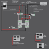
I added in Panel 2, some AWG #'s for the wires, started working on inverters 3 & 4, got to the neutral and got stuck again...sketch is currently incomplete. I wrote some questions in the sketch and attempted to answer below.

1. is neutral a CCC. I would say yes if it is handling any unbalanced 120v current in a 120/240 configuration.

2/3. I would say yes, eliminate panel 1 and 3 since they are only N & G bus bars at this point. However, if I need Hot bus bars for a different circuit is where I will need a new panel.

So the neutral is common to all circuits. In thinking about what AWG the neutral needs to be, if considering a 240 load, you actually wouldn't need a neutral. It's when there is 120 where you need it. If that's the case, then if you could design your 120 loads to balance or offset each other, you go with a much smaller AWG neutral than one would think. I.e., Lets say you have a 240v circuit at 40a, 0 is on the neutral. Lets say you add 10a on L1, neutral needs to be able to handle 10a. Now, lets say you add 10a but on L2...since there is a push pull, that L2 10a should cancel the 10a on L1. So you could say you only need a neutral for 10a whether it be L1 push or L2 pull separately, and in the case L1 10a and L2 10a is simultaneous, neutral is at 0. I hope I have this right. So designing for neutral is really where the calculations come in...it's get's tricky.

So this got me thinking about grounds and grounding rods/grounding potentials. I've heard it mentioned a debate about differences in potentials occurring in the earth at diff areas. So if it's recommended to run a rod at subs in separated buildings, and for ground mount arrays, how does the entire system know what reference potential to use. Is it an average of the potentials from all rods in the earth...or does it have to do with the G/N bond location...because it is closest to the rod at the Main Panel, this Main Panel Rod sets 0v reference, and all the other rods are more like relief valves but because of their distance from G/N bond/Main Panel Rod, they don't affect the authoritative 0v reference...just curious about that.

Proposed_v2
Proposed_v2.png
 
Back
Top