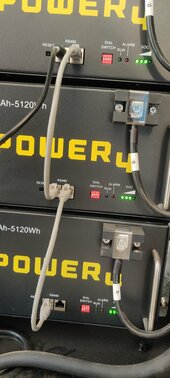
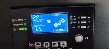
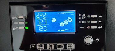
I'm following Will Prowse's instructions to setup a 48v EG4 6500EX solar/battery system. I have 2 x 6500EX's on the wall, and a sub-panel.
Current plan is to move individual circuits from the main street panel, to the sub panel to run off the inverters, with no connection between the sub-panel to the main street panel.
What's different is that I'm adding an A/C IN for the EG4's so that I can charge the batteries from the street, as well as solar. I plan to run Ground, Load, and Neutral to a 60amp breaker in the house main street panel.
My question is on wiring the 6500EX's A/C OUT to the sub-panel. In Wills video, he shows that you can tie neutral and ground on the same bus bar, but said there were exceptions for grid tie, but I didn't see where he elaborated on that. I think mine still counts as off-grid, but wanted to get peoples thoughts.
- For what I described, does this still hold true, or should I separate out Neutral and ground?
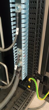
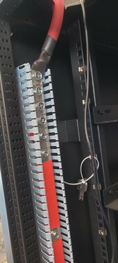
- Can I ground the sub-panel box to the ground in the Main panel, or do I need to run to the grounding rod? From what I see in the house main street panel, they tie ground and neutral together in there, so that had me questioning things.
- I also have a long grounding screw that came with the panel, do I need to install that? I think that bonds the ground and neutral together?