diy solar

diy solar

6500ex "AC" ground wire awg?

Siemens calls for breaker hold downs and line terminal barrier when back feeding panels.

Regarding the line terminal barriers, in my case, I am connecting wires to these lugs in a couple panels so I do not need the barriers, correct? Only on the panel I am backfeeding and NOT connecting to the lugs should I add the line terminal barrier?

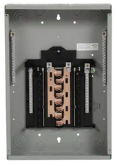
Regarding the breaker hold downs, one of my panels does not have holes in the black plastic copper bus bar thing for the hold downs to screw into, the other panels have these holes. Is there another means for hold down when there is not a screw hole?
 
I need to run the 2 neutrals from inv 1&2 thru a bar, then onto the house via a single neutral. In my diagram I have them in a box, but I was thinking of connecting them to the shop subpanel ONLY to the left side of the panel in the picture below's neutral bar, and connecting all other neutrals to the right neutral bar which would be for the panels loads. Since this is a 125amp bus bar panel, I assume if I ran all neutral on one bar, that could exceed the 80% rule, given 60amp+60amp. Would it be bad practice/confusing if I separated the neutral like this? I assume each neutral bus bar is rated at 125 amps.

Also, would this cause an issue for the Plug-On Neutral feature of this panel? Maybe I should disconnect the Plug-On from the left side so anyone in the future would not connect a Plug-ON...I'm guessing I'm running into bad practice here.
Neutral.png
 
@timselectric you mentioned to me before I could mix inverters connected to the same batter bank, I'm just trying to figure out how they deal with the bank. My understanding is, the inverters simply charge and pull from the batteries, and the bms in the batteries handle the rest. So is the rj45 simply a convenience or something, like for logging?
You don't want to connect the two different systems together.
Only the two of each system.
As far as BMS communications. I don't bother with it.
I don't want my Battery Management System in charge of anything but the battery.
 
Siemens calls for breaker hold downs and line terminal barrier when back feeding panels.

Regarding the line terminal barriers, in my case, I am connecting wires to these lugs in a couple panels so I do not need the barriers, correct? Only on the panel I am backfeeding and NOT connecting to the lugs should I add the line terminal barrier?

Regarding the breaker hold downs, one of my panels does not have holes in the black plastic copper bus bar thing for the hold downs to screw into, the other panels have these holes. Is there another means for hold down when there is not a screw hole?
With a Siemens push on type breaker, there's no need for hold down.
If the backfeed breaker is removed while still on, there are no exposed live parts.
It is required with other style breakers, like square D.
 
You don't want to connect the two different systems together.
Thanks, I didn't mean connecting the two 6500ex to the two 6000xp...I doubt they would communicate. I was just trying to confirm the battery bank communication. I'll have to look at your build thread to see how you do the bms.
 
I need to run the 2 neutrals from inv 1&2 thru a bar, then onto the house via a single neutral. In my diagram I have them in a box, but I was thinking of connecting them to the shop subpanel ONLY to the left side of the panel in the picture below's neutral bar, and connecting all other neutrals to the right neutral bar which would be for the panels loads. Since this is a 125amp bus bar panel, I assume if I ran all neutral on one bar, that could exceed the 80% rule, given 60amp+60amp. Would it be bad practice/confusing if I separated the neutral like this? I assume each neutral bus bar is rated at 125 amps.

Also, would this cause an issue for the Plug-On Neutral feature of this panel? Maybe I should disconnect the Plug-On from the left side so anyone in the future would not connect a Plug-ON...I'm guessing I'm running into bad practice here.
View attachment 186868
It's all rated the same. It doesn't matter where you connect. All on one side is fine. Some on each side is also fine.
 
Thanks, I didn't mean connecting the two 6500ex to the two 6000xp...I doubt they would communicate. I was just trying to confirm the battery bank communication. I'll have to look at your build thread to see how you do the bms.
You have two sets of two units. Connect the two units in each set together. Do not connect the two sets together.
I don't use BMS communications.
 
Do I need to have the 6500ex's create the G-N bond if they are feeding (upstream only) subpanels that are in turn connected to the main that HAS the G-N bond? I will not be wiring/using the AC-IN on the 6500ex's, only the AC-OUT's feeding subpanels. My guess is NO. Can someone please confirm? I believe I can leave the one setting in the 6500ex's that DOES NOT create that G-N bond OFF (i.e. G-N passthrough, or G-N bond relay disable), so as to create only ONE G-N bond, which is at my main panel.
 
Do I need to have the 6500ex's create the G-N bond if they are feeding (upstream only) subpanels that are in turn connected to the main that HAS the G-N bond? I will not be wiring/using the AC-IN on the 6500ex's, only the AC-OUT's feeding subpanels. My guess is NO. Can someone please confirm? I believe I can leave the one setting in the 6500ex's that DOES NOT create that G-N bond OFF (i.e. G-N passthrough, or G-N bond relay disable), so as to create only ONE G-N bond, which is at my main panel.
Correct
 
It's all rated the same. It doesn't matter where you connect. All on one side is fine. Some on each side is also fine.
Did a continuity check, the neutral bars on both sides of the the shop subpanel are connected, I thought they were separate.

I was thinking about the neutral return path for 120v a bit (trying not to overthink it). Regarding the combination of the two neutrals from inv1&2 into one #4 which then spans the 100 feet to the house subpanel feed. The hots go directly (100ft) to the house, but the neutrals I originally diagramed combining in a box with just a neutral bar and ground bar. Then planned to combine them in the shop subpanel instead.

If I did combine the neutrals from inv1&2 on the same neutral bus bar (shop subpanel) as the neutrals from inv3&4's, would I get any sort of voltage leakage or phase noise (if that's a thing) moving between the two separate systems (inv1&2 vs inv3&4) confusing the inverters at all?

I thought the 120v path along the neutral wants to find it's way back to the source via the shortest route, so I was wondering if I wired it like this, would I cause a problem. I could always install an additional isolated neutral bar in the shop subpanel to help separate the two systems path, but I didn't know if this mattered.
If I understand correctly. You should be fine.
The neutral is just the return path of the unbalanced load. All neutrals end up connected together somewhere. (In a common neutral setup, like you have)
 
I’m getting something a little strange. Yesterday I got it all working as designed, but don’t have all my pv built yet so our loads drew more from the bank then what the harvest could supply so I switched the house back to grid overnight but kept everything else on the two invs (3&4) running solely off the bank for the time being. When the well booster pump kicks on, it causes the lights in the house to dim just slightly like how an inductive load does. BUT, the house is on grid, and the well pump is on batteries? The booster is 240v, how can the booster kicking on cause the lights in the house that are getting their power from a different source to dim like that?
 
Everything looks good, it seemed to have stopped. Maybe I was just being over sensitive since I just got everything up and running yesterday.

The dim might be another issue I’ve had for a number of years now possibly related to an outside temperature swing. It started after I replaced a 100amp Zinsco main breaker. In the early morning, things would randomly act like the power would go out for a fraction of a second, until it warmed up, only happened at certain part of the year like early spring. This was before I had any solar stuff setup. Might have been just coincidence.
 
Back
Top