You are using an out of date browser. It may not display this or other websites correctly.
You should upgrade or use an alternative browser.
You should upgrade or use an alternative browser.
6500ex "AC" ground wire awg?
- Thread starter jfharper
- Start date
timselectric
If I can do it, you can do it.
- Joined
- Feb 5, 2022
- Messages
- 18,609
Hot and neutral should be the same size.
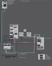
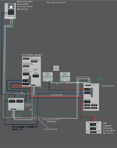
I focused the sketch on the area I thought there was a problem, but after doing so and adding in the neutral I hadn't sketched in the previous version...the problem vanished! I think this sketch works. I thought I had a problem including all active conductors within the same conduit...but it looks like I don't.

Last edited:
timselectric
If I can do it, you can do it.
- Joined
- Feb 5, 2022
- Messages
- 18,609
You still have an extra neutral and ground from the main service panel to the kitchen/ studio sub panel. Neutral and ground should follow the hots. There is no reason for these extra two wires. Maybe they are leftover from a previous change in the diagram.
timselectric
If I can do it, you can do it.
- Joined
- Feb 5, 2022
- Messages
- 18,609
That one is out of place.Good eye...I think the ground needs to stay...I removed the extra N
But there should be one from the outbuilding sub panel to the kitchen/ studio sub panel.
All circuit conductors should be ran together.
Hot/s, neutral, and ground.
There's also a circular neutral loop around the 4 lower panels.
But I don't really see any way to avoid it safety. With all of the back and forth power options. (Interlocked breakers)
So, just leave it as is.
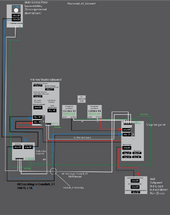
Fixed. So would that circular neutral loop feed any small amount of grid power into the inverters through their AC-OUT, when I have the interlocks as shown below?That one is out of place.
But there should be one from the outbuilding sub panel to the kitchen/ studio sub panel.
All circuit conductors should be ran together.
Hot/s, neutral, and ground.
There's also a circular neutral loop around the 4 lower panels.
But I don't really see any way to avoid it safety. With all of the back and forth power options. (Interlocked breakers)
So, just leave it as is.
timselectric
If I can do it, you can do it.
- Joined
- Feb 5, 2022
- Messages
- 18,609
NoSo would that circular neutral loop feed any small amount of grid power into the inverters through their AC-OUT, when I have the interlocks as shown below?
It's just that it's providing a parallel path. Which should always be avoided.
But I don't see a good way to avoid it. That wouldn't create a worse case, in other "what if" situations.
When you design a system. It's important to think about things that could happen. And how the system would react in those situations.
(Like natural disasters)
In your case. I don't like seeing the parallel neutral path.
But if something was to sever the connection of one path. And it was the only neutral path. The system would still try to work, and create a safety hazard.
So, it's just better to accept the lesser of two evils sometimes.
timselectric
If I can do it, you can do it.
- Joined
- Feb 5, 2022
- Messages
- 18,609
NoWhat if there's a shorter ground path directly to a ground rod? Would it be OK to run the ground separately, instead of running the longer way with the other wires?
The earth is not a good conductor.
The purpose of the grounding system is to provide a low impedance (resistance) path for fault current, back to the source.
The earth is high resistance.
Isn't that where the ground wire ends up at?No
The earth is not a good conductor.
The purpose of the grounding system is to provide a low impedance (resistance) path for fault current, back to the source.
The earth is high resistance.
timselectric
If I can do it, you can do it.
- Joined
- Feb 5, 2022
- Messages
- 18,609
NoIsn't that where the ground wire ends up at?
But the earth is connected to your grounding system. Just like everything else that you want to make safe.
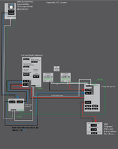
I tried to fix the neutral loop, it would only cost an extra $112 to run two new 100ft #8 run in the same new conduit as the #4, and would share a #4 Neutral. My wire count would increase to 8 in the conduit, derating to 70%, so #4 (95a*.7) 66.5a, #8 would be (55a*.7) 38.5a. I think both those still fall within my breaker amp limits, and one could argue since the #8 would not be ON the same as a set of #4 the 70% derate would not be occurring, it would be 6 wires ON in the conduit at a time...so 80% derate. Do you think it's worth spending the $112 to help the "what if?" Too bad I can't figure a way to safely use the 100ft #4 for a bidirectionally feed/supply depending on which is ON (Grid or Inverter) and ditch the #8 altogether. But all I see is disaster with that scenario.

Side question I've been thinking about...can you mix inverters connected to the same central battery bank? Looking forward, later if I were to replace two of my 6500ex with maybe 6000xp(s) on one side of my design...say inv #3 and #4, would this work if I did not connect the serial cable between all inverters, being of diff type...I would expect them NOT to communicate this way, but somehow manually configured the battery charging values accordingly?
timselectric
If I can do it, you can do it.
- Joined
- Feb 5, 2022
- Messages
- 18,609
I I wouldn't do that. Because the neutral is not following the hots.I tried to fix the neutral loop, it would only cost an extra $112 to run two new 100ft #8 run in the same new conduit as the #4, and would share a #4 Neutral. My wire count would increase to 8 in the conduit, derating to 70%, so #4 (95a*.7) 66.5a, #8 would be (55a*.7) 38.5a. I think both those still fall within my breaker amp limits, and one could argue since the #8 would not be ON the same as a set of #4 the 70% derate would not be occurring, it would be 6 wires ON in the conduit at a time...so 80% derate. Do you think it's worth spending the $112 to help the "what if?" Too bad I can't figure a way to safely use the 100ft #4 for a bidirectionally feed/supply depending on which is ON (Grid or Inverter) and ditch the #8 altogether. But all I see is disaster with that scenario.
View attachment 184854
But I'm not sure which conductors are sharing a conduit or path together.
timselectric
If I can do it, you can do it.
- Joined
- Feb 5, 2022
- Messages
- 18,609
There's no problem with sharing a battery bank between different inverters or systems.Side question I've been thinking about...can you mix inverters connected to the same central battery bank? Looking forward, later if I were to replace two of my 6500ex with maybe 6000xp(s) on one side of my design...say inv #3 and #4, would this work if I did not connect the serial cable between all inverters, being of diff type...I would expect them NOT to communicate this way, but somehow manually configured the battery charging values accordingly?
In my last sketch, there are 5 wires, around the white text saying #4 AWG 100ft neutral. The white, both black, the blue and the red are all sharing the same conduit.I I wouldn't do that. Because the neutral is not following the hots.
But I'm not sure which conductors are sharing a conduit or path together.
timselectric
If I can do it, you can do it.
- Joined
- Feb 5, 2022
- Messages
- 18,609
So if I understand correctly.In my last sketch, there are 5 wires, around the white text saying #4 AWG 100ft neutral. The white, both black, the blue and the red are all sharing the same conduit.
The main service panel, kitchen/ studio sub panel, and outbuilding sub panel, are all at the house. And everything else is at the garage/ barn?
If so, then technically one neutral would suffice. But the code would require two. And two would cover the "what if" situations.
Yep. Ok, I’ll keep two neutrals then.So if I understand correctly.
The main service panel, kitchen/ studio sub panel, and outbuilding sub panel, are all at the house. And everything else is at the garage/ barn?
If so, then technically one neutral would suffice. But the code would require two. And two would cover the "what if" situations.
In figuring out the grey communication cable, the manual shows this:
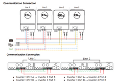
...my design is separating 4 inverters into two sets feeding different subpanel. I think my design is good for when I need to replace a failed inverter, say with a 6000xp or two, perhaps keeping the other 6500ex for the other set if one fails, or something like that.
So my understanding is, I should connect the communication cable as shown in the manual, only so all four can communicate with the battery bank (6 lifepower4s in a rack) thru the master inverter set the eg4, the other three set to USE. In my case, I don't think it matters to keep the sine wave phase synced because my L1's are going to different load centers (same for L2's). Then if I have to replace an inverter in the future with the 6000xp(s) obviously the communication cable is not needed between the two 6500ex's running split-phase and the other new 6000xp(s). I assume I would leave the 6500ex(s) connected to the rack thru the rj45, and would configure the 6000xp(s) with some custom USER settings for charging and what not? But does this work for the 6000xp's if they are not connected to the rack with an rj45?
@timselectric you mentioned to me before I could mix inverters connected to the same batter bank, I'm just trying to figure out how they deal with the bank. My understanding is, the inverters simply charge and pull from the batteries, and the bms in the batteries handle the rest. So is the rj45 simply a convenience or something, like for logging?
Last edited:
Similar threads
- Replies
- 20
- Views
- 612
- Replies
- 22
- Views
- 827
- Replies
- 7
- Views
- 363


