You are using an out of date browser. It may not display this or other websites correctly.
You should upgrade or use an alternative browser.
You should upgrade or use an alternative browser.
EG4 6500EX drop outs
- Thread starter nkhorman
- Start date
Thanks, I did enable it on both units, but I'm unsure that it made any perceived or real difference in terms of flicker in any mode SBU, SUB, or USB.Option 42 can be set on either inverter and the value mirrors to the other one. All you have to do is make the change.
As far as the bonding screw is involved, knowing it affects more than just the relay, I would add back to both. Obviously you would want to kill all power from AC, PV and DC before you open the case.
I've had two or three days since my last post, where I reached 90-99% SOC via PV (no Utility, or other charging method), but not 100% (when the batteries each reach CHGMOS Off), so I don't know if that made a difference in terms of the Drop-Out problem.
Sorry this took until now.Where are you bonded at? Are your PV panels grounded to your AC ground/ground rod? Can you take a closer picture of the inverter wiring?
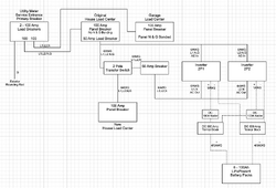
Work and life... and I wanted to have a one-line to show the system, and documentation is a time vampire !
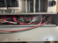
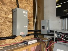
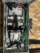
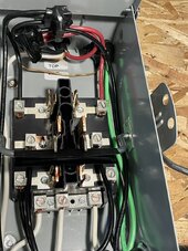
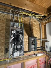
This is an attempt at documenting the system AC and DC parts of the sytem.... minus the PV.
The changes from the original house wiring that I have introduced start from the "Original House Load Center"
This ends up being a common neutral configuration. I was originally going to keep the AC In / AC Out neutrals separate, but i'd need a 3 pole transfer switch to do that, and I only have a 2 pole.
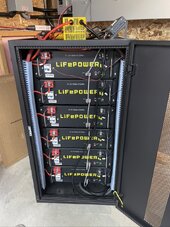
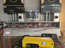
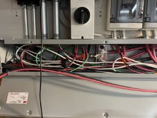
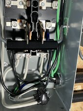
Yes, the only issue is juggling my work schedule to accomodate.Can I get an EG4 technician to give you a call? If so, then please feel free to send me your info and a time period that you would be available to talk via direct message. I think that it would be better to speak over the phone and have someone that has worked on these as much as I have (if not more) take a look at the system and see if we can get everything up and running for you.
Look for a DM with my info.
Here are a couple of videos that I took this morning.
EG4 6500EX Voltage/Frequency Fluctuations #1
EG4 6500EX Voltage/Frequency Fluctuations #2
I attempt to show the flicker, with the relationship to load while showing the waveform on a a scope.
The flicker in the video isn't nearly as pronounced in the video, as it is in person.
The CH1 yellow waveform is from the 2P1 inverter, while the CH2 blue waveform is from the 2P2 inverter.
Triggering is based on CH1, and there is a more or less constant ~800va load on that inverter.
If you watch CH2 in relationship to CH1, you can clearly see the timing and shape changes in response to load changes, and that the less loaded the inverter is, the more distorted the waveform is at the zero-crossing point.
Also, if you watch closely, you can see timming shifts in the phase relationship to CH1.
None of these problems should exist.
To me, there is clear evidence that, these inverters are malfunctioning and are defective.
Infact, Friday night (1/19/2024, it is now 1/21/2024), I had to switch the house to bypass the inverters with the transfer switch, because our freezedryer compressor was physically shaking the whole unit so badly, that you could VERY easly feel how it was struggling to deal with the waveform from the inverter, and I don't want to ruin that ~3500 dollar unit.
EG4 and by extension SS, offered, produced, and sold a product that does not properly perform, and ultimately recognized such, which is why it is now off the market, to reduce liability.
SS and EG4 should make me, and others with these units, whole, without undue burden.
Adam De Lay
Solar Wizard
That’s great investigative work! You can really see the distortion and the flickering. Sorry you’re still having to deal with this.
Has @EG4_Jarrett been able to connect you with someone on the support team?
Has @EG4_Jarrett been able to connect you with someone on the support team?
Thanks.That’s great investigative work! You can really see the distortion and the flickering. Sorry you’re still having to deal with this.
I DM'd him with my info, and we've had a couple of exchanges about timing / availability, but, ultimately, no other contact.Has @EG4_Jarrett been able to connect you with someone on the support team?
So, I dunno if this will be addressed.
fmeili1
Solar Enthusiast
Others and myself have discovered that the problem is only visible (parallel with low load condition), when a specific load is running in parallel on the same phase which makes the inverters reacting like this (with the result of some pulsing LED's). Have you identified such a "bad" load in your situation? @Adam De Lay identified his notebook power supply and in my case it's an old slot machine. The LED pulsing stops suddenly if these type of "bad" loads are disconnected from the inverter.Here are a couple of videos that I took this morning.
EG4 6500EX Voltage/Frequency Fluctuations #1
EG4 6500EX Voltage/Frequency Fluctuations #2
I attempt to show the flicker, with the relationship to load while showing the waveform on a a scope.
The flicker in the video isn't nearly as pronounced in the video, as it is in person.
The CH1 yellow waveform is from the 2P1 inverter, while the CH2 blue waveform is from the 2P2 inverter.
Triggering is based on CH1, and there is a more or less constant ~800va load on that inverter.
If you watch CH2 in relationship to CH1, you can clearly see the timing and shape changes in response to load changes, and that the less loaded the inverter is, the more distorted the waveform is at the zero-crossing point.
Also, if you watch closely, you can see timming shifts in the phase relationship to CH1.
None of these problems should exist.
To me, there is clear evidence that, these inverters are malfunctioning and are defective.
Infact, Friday night (1/19/2024, it is now 1/21/2024), I had to switch the house to bypass the inverters with the transfer switch, because our freezedryer compressor was physically shaking the whole unit so badly, that you could VERY easly feel how it was struggling to deal with the waveform from the inverter, and I don't want to ruin that ~3500 dollar unit.
EG4 and by extension SS, offered, produced, and sold a product that does not properly perform, and ultimately recognized such, which is why it is now off the market, to reduce liability.
SS and EG4 should make me, and others with these units, whole, without undue burden.
There is the key word... visible.Others and myself have discovered that the problem is only visible
It isn't just LED driven lighting.... it's all kinds of loads, resistive and inductive. Noteably, a regular, old-school incandecent light bulb.. 60w... flickers like mad, nearly the same some of the LED lighting that I have, because some of the LED lighting have descent ripple capacitors built-in and they exhibit no flicker.(parallel with low load condition), when a specific load is running in parallel on the same phase which makes the inverters reacting like this (with the result of some pulsing LED's).
Thanks for the suggestion.Have you identified such a "bad" load in your situation? @Adam De Lay identified his notebook power supply and in my case it's an old slot machine. The LED pulsing stops suddenly if these type of "bad" loads are disconnected from the inverter.
Yeah, I went down that road, as stated in one of my early posts... and found a load that caused the symptom... an Apple computer, which is not active now, nor has it been for a while.
That kind of load, a high frequency buck switching power supply, is very common to modern electronics.
Pick anything... Battery chargers for portable electronics, non-portable home entertainment, modern appliances... whatever...
It's ether that kind of load, a switched power supply unit, or restistive, or inductive, or a combination of all three.
I just dont't belive that a modern, battery backed, inverter system can be expected to power resistive / inductive loads exclusively for proper operation.
As an example... the freeze-dryer compressor that I mention above... It's an inductive, resistive, and switching power supply load.
The problem exhibited primarly in the inductive domain... un-sustained frequency and voltage... from an subjective point of view, as I didn't have any measurment equipment at hand, and wasn't willing to gamble/risk the life of that compressor unit in order to objectively characterize the power to the unit, I bypassed the entire house to utility feed from inverter feed.
This negated the solar power usage and utility cost savings for 32 to 48 hours.
I'm not at all happy about that !
This system, as installed, is not a critical load system... It's meant to be able to power the entire house, without qualifcation of load type.
In software, when a user doesn't expect a particular behavior, we call that a bug, not improper operation.
For me, I don't see any way to explain this behavior as improper operation, and nor do I think it improper installation.
Yeah.... I'm gonna say... the type of load that causes this behavior, is a symptom of improper design, not the problem.
Last edited:
fmeili1
Solar Enthusiast
So your think, that the fluctuations are always these, but sometimes just not visible?There is the key word... visible.
Oops, my few still existing incandescent lights are never flicker. Maybe your problem is different from mine (I'm running six of the EG4-6500EX in parallel split phase to drive the whole house). I think you know, that SS told to update to the newest firmware 79.71 and also put all bonding screws in place which should also reduce or solve the flickering.It isn't just LED driven lighting.... it's all kinds of loads, resistive and inductive. Noteably, a regular, old-school incandecent light bulb.. 60w... flickers like mad, nearly the same some of the LED lighting that I have, because some of the LED lighting have descent ripple capacitors built-in and they exhibit no flicker.
I'm running a lot of electronic equipment in my house (many computers, cameras and other electronics). But I identified only the old slot machine and the heating controlling circuit of my 3D printer which causing the phase to get "visibly" unstable. But I never try to check with an oscilloscope if the output is really clean when no LED pulsing occur or just not visible, but still there.Thanks for the suggestion.
Yeah, I went down that road, as stated in one of my early posts... and found a load that caused the symptom... an Apple computer, which is not active now, nor has it been for a while.
That kind of load, a high frequency buck switching power supply, is very common to modern electronics.
Pick anything... Battery chargers for portable electronics, non-portable home entertainment, modern appliances... whatever...
It's ether that kind of load, a switched power supply unit, or restistive, or inductive, or a combination of all three.
I just dont't belive that a modern, battery backed, inverter system can be expected to power resistive / inductive loads exclusively for proper operation.
As an example... the freeze-dryer compressor that I mention above... It's an inductive, resistive, and switching power supply load.
The problem exhibited primarly in the inductive domain... un-sustained frequency and voltage... from an subjective point of view, as I didn't have any measurment equipment at hand, and wasn't willing to gamble/risk the life of that compressor unit in order to objectively characterize the power to the unit, I bypassed the entire house to utility feed from inverter feed.
I think it's not so simple that just a load with complex harmonics with a mixture of resistive, inductive and capacitive (like you've mentioned which is the case for nearly all modern electronic loads) will produce this problem. Most of these load does not produce my problems.
A couple of weeks ago I've started a thread here to discuss deeper and try to analyze this LED pulsing problems. I've got some feedback, that these problems are not unusual also for other, even high priced, brands of HF inverters. Some experts here in this forum explained the reason in comparison with LF inverters and why the HF are more sensitive in principle.
I'm completely with you, the inverters need to be able to run the whole house whichever load is connected. I'm sure that there is more potential for improvement in the firmware for the PID controlling unit which controls the PWM of the inverter - I don't know if it could be eliminated completely (as I already told, even on high priced systems the problem are also known).This negated the solar power usage and utility cost savings for 32 to 48 hours.
I'm not at all happy about that !
This system, as installed, is not a critical load system... It's meant to be able to power the entire house, without qualifcation of load type.
My guess was that the stopping of the LED pulsing is a signal for me that the output is stable and safe - I may be wrong and it would be great to be verified with an oscilloscope. Under this assumption, I'm still trying to "sort of filter" my load which causes the inverter to make LED's pulsing and have at least a workaround.
Maybe, we EG4-6500 owners (I think there are thousands) can try to encourage SS/EG4 to deliver a sort of "final last firmware" update even the inverter is now not longer supported. Even there may be principle more sensitivity in all HF designs regarding this problems, the situation seems worse with this EG4 model compared with other brands.
The EG4-6500EX is based on the Voltronic Axpert Max (MKS2-6500) and many other clones of this base model exists out there. It looks like that others are not so bad hit with this problems compared to the EG4-6500EX - so there should be potential to improve!
In software, when a user doesn't expect a particular behavior, we call that a bug, not improper operation.
For me, I don't see any way to explain this behavior as improper operation, and nor do I think it improper installation.
Yeah.... I'm gonna say... the type of load that causes this behavior, is a symptom of improper design, not the problem.
A little more scope capture this morning, EG4 6500EX Voltage/Frequency Fluctuations #3.
The previous two videos where with the units in SBU mode.
In this one, the units are in USB mode with, PV, 120v load on both phases, and some intermitent 240v load (well pump).
The previous two videos where with the units in SBU mode.
In this one, the units are in USB mode with, PV, 120v load on both phases, and some intermitent 240v load (well pump).
Adam De Lay
Solar Wizard
@SignatureSolarJess can you have a tech reach our to @nkhorman to try and resolve these issues with his 6500s?
SignatureSolarJess
Online Engagement Specialist
- Joined
- Nov 21, 2022
- Messages
- 448
Absolutely! @nkhorman If you would like to reach out to me at engagement@signaturesolar.com, I can certainly get you connected with an associate!@SignatureSolarJess can you have a tech reach our to @nkhorman to try and resolve these issues with his 6500s?
Thank you @Adam De Lay
Status follow-up for those that are tracking...
I'm presently engaged with SS to work on bonding screw installation.
I was given authorization to open the units and install screws. I went the hardware store and bought some, but ultimately, they were incorrect. So i'm now waiting for them to come from SS before I can proceed further.
Of note, after powering down the system (both inverters) AC In, DC, and PV, removing the lower and upper covers, which necessitates removing the cable connected to the LED strip, then reassembling with no changes to the inverter wiring or settings or.... whatever, and re-powering... to my supprise the LED strip started working for the one unit that I dissasembled.
Surprise !
WEIRD !
Soooooo.... loose connection ?
Adam De Lay
Solar Wizard
I do know that any M3, 8mm long screw will work for the bonding screw.I'm presently engaged with SS to work on bonding screw installation.
I was given authorization to open the units and install screws. I went the hardware store and bought some, but ultimately, they were incorrect. So i'm now waiting for them to come from SS before I can proceed further.
I have heard of loose LED bar connections before, so I wouldn't be surprised. At least that's working now...Of note, after powering down the system (both inverters) AC In, DC, and PV, removing the lower and upper covers, which necessitates removing the cable connected to the LED strip, then reassembling with no changes to the inverter wiring or settings or.... whatever, and re-powering... to my supprise the LED strip started working for the one unit that I dissasembled.
Surprise !
WEIRD !
Soooooo.... loose connection ?
Adam De Lay
Solar Wizard
When SS Support saw the voltage fluctuation videos, did they just want to see if the screws resolved anything or were they not much help?
I don't think the videos were specifically addressed.When SS Support saw the voltage fluctuation videos, did they just want to see if the screws resolved anything or were they not much help?
I do remember complements about the volume of information, and that I'd already done pretty much everything that Level 1 Tech would've wanted me to do.
But that, Level 1 Tech wanted to try the screws, and that if the screws don't solve it, then it'd be handed to Level 2 Tech.
Frankly, I didn't expect the screws to make any difference.
I updated the Level 1 Tech this morning, so... I guess I'm waiting for Level 2 Tech.
Zwy
Solar Wizard
I ran a scope on the 6500EX and can tell you it is a losing battle to fix light flicker due to voltage fluctuations.Read this post and watch the videos. https://diysolarforum.com/threads/n...t-without-the-bonding-screw.53547/post-781863
When you look at the sine of the 6500EX compared to the LV6548, you will understand why the 6500EX can't hold voltage. It's internal, the H bridge transition is just terrible. What is the difference internally? I guess some component was substituted or it has to do with the higher voltage PV bus and thus a different component.
You can't fix hardware faults with firmware updates.
Zwy
Solar Wizard
The problem is the H bridge transition. That occurs at the midpoint of the sine as it crosses over. There need to be a slight delay as the bridge switches. I've seen the switch occur too soon and too late.A little more scope capture this morning, EG4 6500EX Voltage/Frequency Fluctuations #3.
The previous two videos where with the units in SBU mode.
In this one, the units are in USB mode with, PV, 120v load on both phases, and some intermitent 240v load (well pump).
I'd press for your money back or credit on different units. Bonding will not fix this problem. You could fry electrical devices in your house, it's not worth it.
Similar threads
- Replies
- 197
- Views
- 6K
- Replies
- 24
- Views
- 882
- Replies
- 5
- Views
- 241
- Replies
- 11
- Views
- 421


