diy solar

diy solar

AC Outlet Possibilities

redpostbox

New Member
Joined
Jan 26, 2021
Messages
8
Hello everyone,

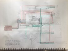
I am a newbie at this and I am still trying to figure out a solar system that works for my future off-grid house.

1) For every sine wave power inverter (assuming it comes with one outlet slot) how many AC outlets can I 'branch out'? Just like a normal house, I would like to have a few outlets in different rooms. Does that mean I need 1 inverter for every AC outlet (which is my presumption now)?
2) If it is possible to have more than 1 AC outlet per inverter, how do I know/ calculate how many AC outlets I can have per inverter?

Many thanks!


Shaun
 
Welcome to the forum.

The inverters with simple plugs aren't the best for your application. Each plug is typically limited to 15A, and branching them out is messy. Better to get an inverter with an actual terminal block.

1611726352399.png

The terminal block on the right can be used to pass L N and G to a panel buss and supply the entire panel with breakers for every circuit. You'll still be limited to the peak power of the inverter, but you won't be limited by the 15A plug.
 
Hi snoobler,

Thank you for your reply. That was really helpful to know I should be on the lookout for an inverter with a terminal block. Do you happen to have a photo of how the L N and G would branch out to multiple outlets? I am having trouble imagining it's installation.

Now that I know it is possible to have multiple outlets with only one inverter, what should I be on the lookout for when choosing an inverter? In my limited knowledge, if the inverter says 2000w, it just means that it's the total wattage it could supply per number of electrical devices to have switched on at the same time. Am I correct?

Any other spec technicalities to look out for when choosing an inverter if my intention is to have multiple outlets?
 
Also, you mentioned peak power, which is something that is written on all the inverters I have seen so far. What does it mean to have a 1000W inverter with 2000W peak power? Does that mean I have keep using it close to 2000W or it's just a fail-safe just-in-case-you-overload kind of scenario?
 
Ideally, you'd wire as I described. Inverter to a breaker panel and then the panel to the outlets. Picture an existing house: You have grid power coming in from the power company distributed to the breakers in the panel and each of those breakers provide power to the various branches in the house. The inverter replaces the grid power.

Peak power in many cases is misleading. An inverter as you describe could operate continuously at 1000W. It can tolerate brief surges to 2000W, but this may be for fractions of a second and have no real meaning. That's typically the case with high frequency inverters. These are characterized by their typically cheaper prices and light weight. They are a very poor choice for starting motors.

Low frequency inverters have massive transformers and can handle very large surges, 2-3X for a meaningful period of time, up to 30 seconds. These are great for starting motors.
 
That makes a lot of sense. Thank you :)

1) What is the standard cable for this L N and G connection to the inverter? I am assuming that has to be the most important part to get right if I want multiple breakers/ outlets.

2) How do I recognize low frequency inverters from high frequency ones when deciding to buy?
 
1) 6 awg is a good start.

2) low frequency are HEAVY and have a meaningful 2-3X peak current rating that lasts for 20+ seconds.
 
Can you check if my understanding of the grid (attached photo) is correct?

Assuming that I have an inverter that handles 2-3,000 watt and it goes into a C63 amp Isolator and then 6-20 amp MCB to supply electricity to sockets and appliances. I am using only 5 items as an example only, I know I will need a lot more, hence the wattage.

I am drawing this grid based in the installations of a regular house. I wonder if this still applies when using an inverter or there is a slightly different configuration? Also if I still need an earth grid and grounding it outside.

Thanks for your feedback again!
 

Attachments

  • IMG_8581.JPG
    IMG_8581.JPG
    54.9 KB · Views: 12
3000W ÷ 120VAC = 120V/25A (simple math of it)

If you have an Inverter that can be "Hardwired" meaning it does not have plugs*, it can be wired to an AC Sub-Panel (a panel without a Master Breaker) you can distribute standard 120VAC circuits with breakers from there. You can have 10 circuits if you want BUT you would not be able to exceed 25A draw in total at any single point in time, otherwise, the inverter will trip.

plugs* : Inverters with such plugs are usually considered "Car Inverters" and are for all intents & purposes lightweight and not intended for constant use, just for occasional use. They are also more often than not, High-Frequency Inverters if designated as "Pure Sine". HF Inverters are terrible for motors like fridge/ac compressors, tools like table-saws or well pumps.

Below is a diagram that is pretty much self-explanatory.
120VAC incoming from the powerhouse and distributed to the two "legs" with a bridge wire.
If this was 240VAC incoming, then the Bridge Wire would be eliminated and Hot-1 would goto Terminal A, Hot-2 would goto Terminal B provisioning the two 120V legs as normal.
** My system is wired ONLY for 120V as I do not need 240V. It is setup to be able to be converted to 240V/100A (using the 8/3 wiring) or 240V/200A (using the aditional 6/3 wire that is already wired in place) for future growth/change.

There is more information on Page-2 of my "About my System" page, link in my signature.

1608234476503-png.30542
 
Thank you for your input. It makes more sense now.

I am in Malaysia and using 240V 50Hz. It seems like I ll need an inverter of 15,000 watt if I want to be able to have a 60A grid like a normal house. Not that I will be using that much power on a daily basis but assuming I have indoor and outdoor lights, fans, fridge, a water pump, wall outlets, and a PC, it feels like I will need more than 25A.

Is my calculation correct and it is even possible/ feasible to have an inverter that size?

Yes, planning to get an inverter that I can hardwire. Does it mean those that can be hardwired have low frequency naturally? I have been looking at many inverters online and some of them do not mention if they have low or high frequency.

Also, why is it wrong to have a Master Breaker? I assumed it'll make the entire circuit safer?

Thanks again.
 
There are High (HF) & Low (LF) Frequency inverters in all sizes.
For 15,000W Inverter, you will certainly want a 48V battery bank.
15000W÷48V =312.5A pull from battery bank.
240V x 100A = 24,000W. 24,000W ÷ 48V = 500A.

There is nothing wrong with having a Main Breaker.
My system has a separate independent AC breaker between the Inverter & PH Sub-Panel. It's juts a different way of doing this and using only 120V.
With a 220/240 System, I would run from the Inverter to the Main Panel Master breaker.
* Single Phase like you have is different than 240V/Split Phase as used in Canada (I'm a Canuck EH !)

Be VERY Careful looking at descriptions & specifications because the Devil IS in the details !
We had one fellow who just tried to hooking a European 220V/50Hz Single Phase to a US 240V/60Hz Split Phase, did not go well.

Make VERY Certain & Verify that ANY inverter you are looking at supports 240V/50Hz. Volton Nominal Voltage is rated for 230VAC/50Hz.

REFERENCE INFO:
 
Thank you for your input. 48V makes sense since I am considering higher amp for my place. I will have to double my battery capacity as I was considering 24V.

I would also like some clarifications about grounding my system. Yours for example, you only ground your charge controller and main breaker panel (if I am reading your diagram right) and not your inverter and AC outlets.

1) I was under the impression that grounding for an off-grid property is the same as the grounding for an on-grid property. For example, live, neutral, and ground wires present on all the AC outlets and wirings back to the main breaker panel. But I have seen tutorials where only live and neutral wires are used. Why the difference and what are the safest grounding preferences/ guides for off-grid property?

2) Should I ground all electrical devices involved if they have built-in live, neutral, and ground ports? Like if I see 3 ports in that device, I can just install the ground wire too?

3) Can all the ground wires from different electrical components be connected to the same copper rod(s) and buried to the ground or some of them must be grounded separately and far from each other?

I am sorry if my questions seem noobish. I am learning this entire thing by myself and physics wasn't my strongest subject back in school. Just want to make sure I don't fry my system up.
 
Everything is fully grounded in my system, everywhere.
1) Solar Panel framing & rails are independently grounded.
3) The AC Wiring is ALL grounded. Actually grounded to my Well Casing which is 6" and 20'/6.1m deep.
3) The inverter, solar controller are grounded, as is the genset.
I also have Lightning Protection on the system and "wet areas" like the washroom are CGFI as well.

(1) I most certainly would NEVER use an ungrounded system as I am landbased. A Vehicle is a different beast altogether and that may be where some of the confusion originates based on your comment.
(2) Everything should be grounded appropriately as per your electrical code. You have to review your electrical codes & best practices for your region, it varies somewhat because different region have unique differences.
(3a) Here all AC Wiring and AC devices use a Common Ground which includes all electrical panels and circuits. Everything is bonded together so ultimately in my case, all grounds lead to the Well Casing.
(3b) The solar Panels are grounded independently to a grounding plate (30x30cm galvanised plate) so that is isolated.

If you do not know something ASK ! The only stupid question is the one that is not asked and that is the one that causes people the most problems. Never be afraid to ask questions, only stupid people don't ask and make assumptions which more often than not, leaves them with major problems and possibly a personal disaster on their hands.

A couple of links to Code Docs which I believe apply to you, there may be more up to date & current ones but you'll have to look around for them.

MALAYSIAN MS 1979:2015 STANDARD Electrical installations of buildings - Code of practice (First revision)

Suruhanjaya Tenaga GUIDELINES FOR ELECTRICAL WIRING IN RESIDENTIAL BUILDINGS 2008 EDITION www.st.gov.my

Hope it helps, Good Luck
Steve
 
Thank you, that was very very helpful!

Another question I have about grounding is, I am thinking of building a boat house. Nothing fancy, but would like to have some lights, USB charging ports and if possible, one or two AC outlets. Is it possible to put a solar system in seeing there is no way I can ground my cable since it is a floating structure? I have seen boats with solar system. How do they do it?
 
Back
Top