diy solar

diy solar

Active balancer, make it smart!?

The ONLY time to balance is in the knees. You need the voltage delta for balancing which you will not see in the flat part of the curve.
So there are 3 ways of doing that
1. Cell voltage >3.4V alone
2. Putting a limit on delta V - I use 20mV alone 16S 300Ahr LiFePO4 ( with no cell voltage control)
3. Using cell voltage >3.4V and delta V - 5-10mV
 
So there are 3 ways of doing that
1. Cell voltage >3.4V alone
2. Putting a limit on delta V - I use 20mV alone 16S 300Ahr LiFePO4 ( with no cell voltage control)
3. Using cell voltage >3.4V and delta V - 5-10mV
I think you’re reading to much into it.
Just set the balance to start and continue at anything over 3.4 volts. 3.42 is where mine start. Mine continues till it balances down to .002 difference or drops below 3.42vpc.
 
Last edited:
I think you’re reading to much into it.
Just set the balance to start and continue at anything over 3.4 volts. 3.42 is where mine start. Mine continues till it balances down to .002 difference or drops below 3.42vpc.
Not all active balancers work this way.
Explaining how different active balancers can be setup
1. Heltec Capacitor type - some use the on/off tabs to detect cell voltage so they only operate in the knee. There is no ability to adjust delta V cut off.
2. The Standalone JK active balancer does not have the ability to turn on/off at a cell voltage but you increase delta V and this stops it from working on the flat part.
3. Yes JK BMS and Neey and others can adjust both cell voltage and delta V cut off.
 
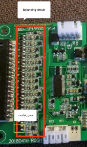
Would be a dream come true if a knowledgeable person could find the passive balancer circuit on the jbd bms and find out where one could solder on the on-off cables so that the heltec gets also activated whenever the passive balancer does!
an alternate option that might be slightly more prone to failure is to have a small microcontroller read the cell voltage data from the BMS serial interface and activate based on the minimum volt and delta etc. this is the approach i am set on
 
Not all active balancers work this way.
Explaining how different active balancers can be setup
1. Heltec Capacitor type - some use the on/off tabs to detect cell voltage so they only operate in the knee. There is no ability to adjust delta V cut off.
2. The Standalone JK active balancer does not have the ability to turn on/off at a cell voltage but you increase delta V and this stops it from working on the flat part.
3. Yes JK BMS and Neey and others can adjust both cell voltage and delta V cut off.
Back when you asked “which is fastest” I didn’t know you were already an expert.
 
I have just gotten my esp32 reading the BMS data thru uart. Next step will be to control the Heltec balancers instead of the voltage sense circuit currently used. Should be easy enough but may not get around to it till next weekend.
 
Last edited:
Hello to all! I would like to control the Hankzor 5A 4s Active Balancer with the programmable load output of my Victron MPPT Solar Charge Controller. As Hans Kroeger said further up in this thread that should be possible using a P-Channel Mosfet. Can I use an IRF4905 for that purpose - as it's easiely availible? It has a Vgs of ± 20 V and a Threshold Voltage of -4V.
How do I wire it up? Will it be enough to connect the gate to the positive terminal of the load output and the source and drain to the two soldering pads on the balancer? Somehow I have the feeling I am missing something.... Maybe a 10K resistor from the gate to the nagative terminal of the load output?
Cheers
Paul

P.S.: Never mind - I managed myself. Can confirm that an optocoupler (PC817) followed by a IRF5305 P-Channel MOSFET works flawlessly to switch on/off the balancer from the load output of a Victron MPPT. Tested the virtual load output (uart TX alternate function) as well. That works, too.
 
Last edited:
Would be a dream come true if a knowledgeable person could find the passive balancer circuit on the jbd bms and find out where one could solder on the on-off cables so that the heltec gets also activated whenever the passive balancer does!
It should be theoretically possible because there must be a mosfet or so to switch the passive balancer circuit on and off.
Once that mosfet is found one could solder one cable in front and one behind it to act as a switch. Since the current is super low there shouldn't be an issue...?

Would be a neat and cheap solution because then everything could be programmed and monitored from the stock app without the need of any extra devices etc..
This hack could be used with any smart bms which has a passive balancer.

@Hans Kroeger could this work? Have you ever tried out something like that with your bms or do you think that can't be done? I believe you know very well how a passive balancer circuit gets switched on and off since you have designed and build one yourself as well!
 
IMG_20221201_215723.jpg
It seems one has to choose a mosfet of one single cell (probably best "the problem cell" of ones pack) to solder ones on-off cables on to. So whenever that cell gets balanced the active balancer would also wake up to do its job.

Any thoughts concerning this theory? Could this work?
 

Comment on first video: Hopefully this addition will start to be incorporated into other model BMS's.

On the BMS that provides enable control to active balance. Check if the enable control line from BMS disables external balancer for a moment when BMS is making cell voltage measurements.

The BMS still needs to manage cell voltages for low and high cell voltage shutdown. You don't want high active balancing current to influence the BMS cell voltage measurements. Balancer current influence will be worse on BMS cell voltage readings when there is little to no charge current dominating cell overpotential voltage bump up of cells due to charging current. Same charge current is applied to all cells, but balancing current is not equally applied. Five amps of balancing can slump or boost a cell voltage by 15-25 mV when there is little charge current to dominate cell overpotential voltage.

If it does shut down balancer when BMS makes voltage measurements, you could also share common sense lines to cells without worry of balancing current causing voltage drop on sense lines during BMS voltage measurements, greatly reducing the 'rats nest' of wires.


On the second video, my comment on the video was:

Not interested in any balancer that requires all cells to be above 3.4v first. Imagine when you have 16 cell system. Probability to lose the race for one cell to go overvoltage increases with 16 cells with a wider SoC spread likely.

Starting the race when first cell goes over 3.4v gives you more balancing time and better chance to achieve balancing before highest SoC cell hits overvoltage.
 
Last edited:

On the second video, my comment on the video was:

Not interested in any balancer that requires all cells to be above 3.4v first. Imagine when you have 16 cell system. Probability to lose the race for one cell to go overvoltage increases with 16 cells with a wider SoC spread likely.

Starting the race when first cell goes over 3.4v gives you more balancing time and better chance to achieve balancing before highest SoC cell hits overvoltage.
I am pretty sure the powerpaul balancer works the same as the modified one i got from Hankzor. It only reads the voltage of the first cell. Once the first cell goes above or below the defined voltage thresholds the balancer gets activated or deactivated.
BTW all other capacitive balancers work in the same way (monitor only voltage of first cell), just the on off thresholds differ.
 
@MullerEnergy-Australia may know all about this but maybe commercial in confidence stuff with JBD?
Sorry, I just saw this tag. Yes, it's possible, but only if you use an optocoupler. This ensures that you don't impact the BMS with the active balancer. Unfortunately, as I understand it, it's different with each BMS type, so I can't give a general answer. And when it comes to our type of BMS, while I could reveal it, I'll just recommend to buy our BMS instead! ? (If someone already has this same BMS I could probably be persuaded to post a picture of where to connect, but as I understand it, there's virtually none of this BMS out there other than ours).
 

Comment on first video: Hopefully this addition will start to be incorporated into other model BMS's.

On the BMS that provides enable control to active balance. Check if the enable control line from BMS disables external balancer for a moment when BMS is making cell voltage measurements.

The BMS still needs to manage cell voltages for low and high cell voltage shutdown. You don't want high active balancing current to influence the BMS cell voltage measurements. Balancer current influence will be worse on BMS cell voltage readings when there is little to no charge current dominating cell overpotential voltage bump up of cells due to charging current. Same charge current is applied to all cells, but balancing current is not equally applied. Five amps of balancing can slump or boost a cell voltage by 15-25 mV when there is little charge current to dominate cell overpotential voltage.

If it does shut down balancer when BMS makes voltage measurements, you could also share common sense lines to cells without worry of balancing current causing voltage drop on sense lines during BMS voltage measurements, greatly reducing the 'rats nest' of wires.


On the second video, my comment on the video was:

Not interested in any balancer that requires all cells to be above 3.4v first. Imagine when you have 16 cell system. Probability to lose the race for one cell to go overvoltage increases with 16 cells with a wider SoC spread likely.

Starting the race when first cell goes over 3.4v gives you more balancing time and better chance to achieve balancing before highest SoC cell hits overvoltage.
Good comments!
The cell voltage measurements work fine and balancing does not cause any read errors on it. In my mind (and feel free to disagree) this isn't really an issue, regardless of whether the balancing is stopped for voltage measurements or not. While it's listed as a 5A balancer, this is only at the very extremes that it will have this sort of current and the lower the voltage difference, the lower the current flow.
So let's assume the BMS didn't disable balancing and you have a 5A balance flow from the highest cell to the lowest cell. It would quickly reduce the voltage of the highest cell and the charging would be enabled once more. The voltage difference will decrease each time and hence the balancing current.
While the charging will cut in and out a few times this isn't an issue in any way.
Given it's a 250A BMS, I would assume that the cells it's connected to would be at least 100Ah or more, in which case a balancing current of say 1A won't make too much of a difference to the voltage readings. Plus (again, in my opinion), the high voltage disconnect voltage is a little bit arbitrary, whether it's in actual fact 0.05V higher or lower than the set point, really doesn't make any real life difference as to how the battery operates.

As for the wires, yes, they could certainly be optimised in the future.
 
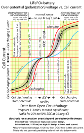
It takes very little cell current to pull cell overpotential 5-20 mV off of true rested SoC cell voltage and there is an equilibrium recovery time of 30-180 seconds. This can cause BMS to make wrong decisions on which cell needs balancing, particularly in flatter part of discharge curve below 3.4v cell voltage. This can cause a problem when there is only balancing current going on, with no charge or discharge current across all cells from inverter/charger.

When there is significant charging current (greater than balancing current) also happening, the large charging current sets the cells' overpotential across all the series connected cells and makes the balancing current have insignificant impact on cell overpotential voltage shift from the small additional balancing current.

Allowing balancing only above 3.4v on a cell accomplishes a couple of things. First, it is out of flat discharge curve of normal cell operating range making it easier for BMS voltage sensing to tell which cell needs balancing. Second, balancing only above 3.4v pretty much dictates there will charge current happening since it requires charging current to get a cell above 3.45v in voltage. Having charging current applied to all cells helps make any individual cell additional balancing current induced overpotential voltage shift insignificant.

There will be a short period after charging is completed that cells will be above 3.45v before continued balancing will bleed off electrode surface charge. Cells will drop to 3.45v due to continued balancing dump in a short period of time (few minutes) as the surface charge capacity is very small (approx. only 0.01% of cell capacity).

Downside of balancing only above 3.4v, during charging, is you have a time race between accomplishing all cell balancing before the highest SoC cell reaches overvoltage limit setting of BMS, tripping a charge shutdown. The greater the ratio of charge current to balance current, the less time you have to accomplish balancing of all cells before a possible cell overvoltage BMS shutdown. If you periodically (once a month) do a full charge to absorb level, you will maintain good cell balancing and avoid the cell overvoltage shutdown.

LFP Over-potential Chart.png
 
Last edited:
Sorry, I just saw this tag. Yes, it's possible, but only if you use an optocoupler. This ensures that you don't impact the BMS with the active balancer. Unfortunately, as I understand it, it's different with each BMS type, so I can't give a general answer. And when it comes to our type of BMS, while I could reveal it, I'll just recommend to buy our BMS instead! ? (If someone already has this same BMS I could probably be persuaded to post a picture of where to connect, but as I understand it, there's virtually none of this BMS out there other than ours).
Many thanks for your reply and ingenious idea + solution how to make these active balancers smarter!
I as many here would really appreciate if you could be persuaded to kindly post a picture of where you connected the optocoupler on your bms model and which optocoupler you used for that. It would be a great and appreciated addition to the various ideas and solutions we already have shared here. Anyway whatever you choose we respect your decision.
On a sidenote i think it would also not really interfere with your sales since in the official jbd store on AliExpress you can't even find a 250a 4s bms, there is presently no alternative to yours in that segment. On the contrary, it might inspire those who use and need a high amp 4s smart bms to buy yours since they got touched by your innovative spirit and expertise and saw how well and seamless you implemented this ingenious idea.
 
Not sure if anyone has tried this or not but i am going with XY-CD60L which does what everyone here is trying to discuss about disconnecting the balancer below a certain voltage. After ordering a couple of different boards i will settle on CD60L or the newer version with bigger relay CD-63L. key for my search was discharge controller and setup the disconnect for a certain voltage (eg. 53v and connect at 54v to deactivate/activate the balancer)
No modifications required.
Vin connects to battery and OUT connects to balancer.

 
connected XY-CD60L yesterday with my 1A JK active balancer which i have for a few years now connected to my old BYD batteries from battery hookup. worked as expected. tuned on at settings in the board 53.5v (it shows about 1v higher than the actual voltage about 52.5v) and turn off at 52.5V (actual battery voltage about 51.5v). my batteries at not at best of health capacity wise and they are used/abused batteries. i can try to charge up to 55v but drops to 53.3v (i would estimate about 80% capacity) within 20 minutes of start of discharge. i remember vaguely at the time it said to expect about 2000 cycles from the batteries, i have it connected for past 3 years now an i feel the pinch of it discharging quickly for my loads.
 
Back
Top