Hans Kroeger
New Member
- Joined
- Dec 30, 2020
- Messages
- 128
I guess so, but I really don't care. The price is so low and I want to test this very unit!Do you mean you payed for the 8s version but they will send you one single 4s version instead?


I guess so, but I really don't care. The price is so low and I want to test this very unit!Do you mean you payed for the 8s version but they will send you one single 4s version instead?
That's very generous of you! ?I guess so, but I really don't care. The price is so low and I want to test this very unit!
Hi BradAlright, I'm writing software that communicates with a bms for logging time series database for graphing, but also to trigger relays for controlling things like active balancers, and to control loads based on excess solar, etc..
It communicates via BT to the BMS, and runs on a raspberry pi. So when I'm done hopefully it'll just be an image you can flash to the sd card, and get down to business.
HI Max,That's very generous of you! ?
That shop was also very generous towards me. I did order a 20A BMS from them and on the day they shipped it they sent me a message "SENT YOU 30A". That was a pleasant surprise!
Hi HansHI Max,
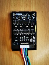
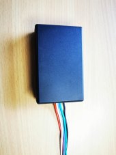
today I received 2 of the concerned balancers. I tested both Balancers with my 12 V battery simulator. I could not find out how to operate theses modules in a useful manner. Only one thing is obvious, the touch pad allows to turn on or off the Balancer manually. However there is certain delay time of some seconds.
The status LED is reacting slow when turning off. But the power consumption shows immediately if the module is on or off.
I could not find out how to get the Balancer turn on by itself, if the cell voltage goes above a certain voltage (e. g. 3.25 V). I also could not find out how the Balancer turns itself off if the voltage drops to a value below 3.25 V.
May be there are very long delay times, but waiting for a couple of minutes didn't reveal anything useful.
Without a manual this Balancer seems to be useless.
By the way, the balancing function seems to work. However, I didn't make any detailed measurements, because I believe it is a waste of time.
Regards Hans
Alright, I'm writing software that communicates with a bms for logging time series database for graphing, but also to trigger relays for controlling things like active balancers, and to control loads based on excess solar, etc..
It communicates via BT to the BMS, and runs on a raspberry pi. So when I'm done hopefully it'll just be an image you can flash to the sd card, and get down to business.
Sounds like a good project.
Will your software for the Raspberry Pi work for the Overkill Solar BMS? I run two or their 8s 24vdc 100amp BMS and looking to get BMS(s) logging database for graphing etc.
Hello,Which is more effective?... Condenser type balancer or INDUCTIVE type active balancer
Both work, but effectiveness also depends greatly upon the detailed design.Which is more effective?... Condenser type balancer or INDUCTIVE type active balancer
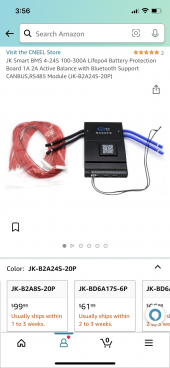
Hi there, I am 100 % with you! Nevertheless I would like to add one comment. I have modified the active 5 A Heltec balancers (flying capacitor) such, that the balancer turns on at 13.5 V total voltage (4 cells), and turns off at 13.3 V.I’ve retired all my Heltec balancers and keeping my Neey clones .....Or you could just go with a JK bms that will do it all that starts at $100 on Amazon depending on your needs (amps, cell count, balance current & connectivity). The JK has the best app on the market IMHO for android or iPhone. PS that was my video that someone posted at #6 of this thread (that’s system is gone now but it seemed to work, just the Daly bms went wonky.
Yes, 4 S version..... I guess you are right. But I am wondering why there is still 8 mA after the Low Voltage shut down. 8 mA can deep discharge a 100 Ah Battery after one week.Is your JK bms a 4S version? If so I betcha they have a little buck boost incorporated into it to keep the control board alive. A buck boost idle current might be what you are seeing.
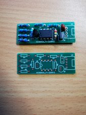
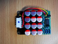
Not at all. It brought my cells to within 10 mv within days versus the many weeks it would have taken the passive balancing of my BMS to get there. I do not agree with the assumption in that example that the top balance is lost over time. That has not been my experience.Have you also experienced that your non-smart cheap active balancer (example picture attached) causes your painstakingly top-balanced battery to loose its top-balance over time!?
A lot has to do with the battery use patterns whether or not a balance always or only above 3.4vpc will cause a wild delta. That’s why there’s been so much controversy. I never wanted to tempt fate knowing my luck.Yes, 4 S version..... I guess you are right. But I am wondering why there is still 8 mA after the Low Voltage shut down. 8 mA can deep discharge a 100 Ah Battery after one week.
True after overdischarge disconnect (UVP) . I doupt that the converter is still on after the final "Power Off" shut down which sets the BMS in a deep sleep mode. Will check if the is ripple voltage on the power lines.....Just buck boost connected doing nothing(standby)draws amps.