Which balance lead wire on the JK active balancer do you connect and disconnect with the relay on the XY-CD60L to turn the balancer on and off?connected XY-CD60L yesterday with my 1A JK active balancer which i have for a few years now connected to my old BYD batteries from battery hookup. worked as expected. tuned on at settings in the board 53.5v (it shows about 1v higher than the actual voltage about 52.5v) and turn off at 52.5V (actual battery voltage about 51.5v). my batteries at not at best of health capacity wise and they are used/abused batteries. i can try to charge up to 55v but drops to 53.3v (i would estimate about 80% capacity) within 20 minutes of start of discharge. i remember vaguely at the time it said to expect about 2000 cycles from the batteries, i have it connected for past 3 years now an i feel the pinch of it discharging quickly for my loads.


You are using an out of date browser. It may not display this or other websites correctly.
You should upgrade or use an alternative browser.
You should upgrade or use an alternative browser.
Active balancer, make it smart!?
- Thread starter Vi s
- Start date
Which balance lead wire on the JK active balancer do you connect and disconnect with the relay on the XY-CD60L to turn the balancer on and off?
Most negative BLACK wire and most positive the last RED wire on active balancer.
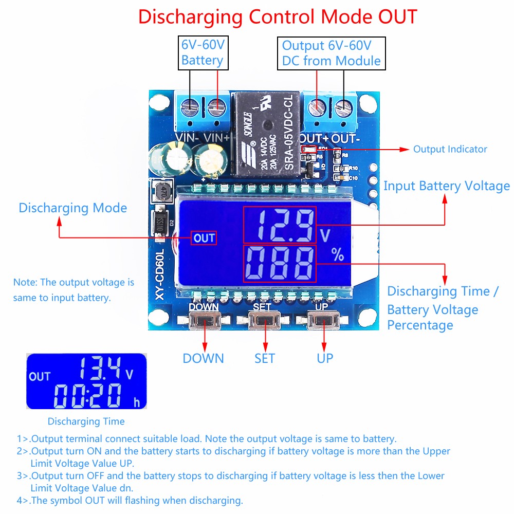
Battery terminals connected to Charger input in the picture (Vin-,Vin+) the load side is connected to active balancer (out+, out-) and it is setup for discharge control mode so the display should be showing OUT as in picture.
Lithium Battery Charge Controller Battery Protection Board 6V-60V LCD Display Battery Charging Control Board
Lithium Battery Charge Controller Battery Protection Board 6V-60V LCD Display Battery Charging Control Board
In this mode with XY-CD60L can you be sure there is no voltage drop thru the controller circuit? ( compare Vin- Vin+ voltage to Out- Out+ve Voltage).
Is there a relay switch output mode that you could connect and disconnect the most +ve balance lead?
Is there a relay switch output mode that you could connect and disconnect the most +ve balance lead?
I have not traced circuit but it says in the description that it is just a voltage control switch and just switches the output on or off and yes it is just connecting vin+ to out+ via relay.

So it should only be necessary to connect to battery on input side and and most +ve balance wire to Out+ and -ve balance wire can stay on balancer
most -ve can stay on the "battery" but you still a vin+ and vin- for the board to operate, which is acting as the power source for the board so that means you will have two wires on battery -ve. one from the board Vin- and one from balance -ve. i just think it is more ideal to make it simple and have the balancer wires connect on the board that way power goes in from battery to board +Vin and -Vin and power comes out via out- and out+ and goes to balancer.View attachment 128904
So it should only be necessary to connect to battery on input side and and most +ve balance wire to Out+ and -ve balance wire can stay on balancer
CrossStreet
New Member
- Joined
- Jul 4, 2022
- Messages
- 45
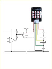
I am thinking of a way for connecting XY-CD60L to heltek type balancer's Run switch. Maybe one side of the switch is at the most negative or most positive potential already, which should allow to use XY-CD60L.
Last edited:
CrossStreet
New Member
- Joined
- Jul 4, 2022
- Messages
- 45
I think I'll go with a relay like this one - "A30 Controller" to connect/disconnect the Run switch on my 16s 5A flying capacitors balancer (the very usual one, like heltec).

DC Voltage Detection Charging Discharge Monitor Relay Modules Switch X4V0 | eBay
Working Current: 8mA/24V(relay open, LED displays OFF about 4mA/24V); 58mA/24V(relay closed). DC 6~80V relay interface board with 2 buttons for easy operation. so the electric load above DC60V load current is less than 10A.
www.ebay.co.uk
Last edited:
That looks exactly like xy-cd63l without the case.I think I'll go with a relay like this one - "A30 Controller" to connect/disconnect the Run switch on my 16s 5A flying capacitors balancer (the very usual one, like heltec).
DC Voltage Detection Charging Discharge Monitor Relay Modules Switch X4V0 | eBay
Working Current: 8mA/24V(relay open, LED displays OFF about 4mA/24V); 58mA/24V(relay closed). DC 6~80V relay interface board with 2 buttons for easy operation. so the electric load above DC60V load current is less than 10A.www.ebay.co.uk
CrossStreet
New Member
- Joined
- Jul 4, 2022
- Messages
- 45
I think it is different. The ebay one (A30 Controller) controls relay to flip an independent contact, while xy-cd63l connects a contact that is at a voltage potential. I don't know how my balancer will react if I raise the Run switch to battery positive or battery negative.That looks exactly like xy-cd63l without the case.
i had ordered XY-L30A and XH-M604 earlier both come with A version of relay. i ordered JQC3FF-5V-1ZS(5pin) relays to replace the existing relay on the board and modify and switch the the relay contact independent of input.
Does anyone have experience with using a transistor or FET instead of a relay to switch the run port on the balancer? I'm thinking of a small board with e.g. ESP8266 that reads all cell voltages from my BMS via RS485 and switches the balancer on or off depending on the load current and cell voltage.
It is therefore necessary to know the electrical characteristics of the balancer's running connection.

It is therefore necessary to know the electrical characteristics of the balancer's running connection.
Way too complicated and expensive for this thread. you are almost leaning to a BMS functionality.Does anyone have experience with using a transistor or FET instead of a relay to switch the run port on the balancer? I'm thinking of a small board with e.g. ESP8266 that reads all cell voltages from my BMS via RS485 and switches the balancer on or off depending on the load current and cell voltage.
It is therefore necessary to know the electrical characteristics of the balancer's running connection.
View attachment 131350
I control mine with a voltage sense circuit and relay. Data from my BMS's is gathered with an esp32 so I do intend to use this to control the balancers. I don't believe there is any power thru the run, just signalling the onboard controller. Worst case I will wire up a transistor to the esp32 in place of the relay. Just won't be doing this till March.
CrossStreet
New Member
- Joined
- Jul 4, 2022
- Messages
- 45
I had good success with controlling the Run switch on my balancer via that A30 controller. Extra difficulty for me is that the battery is made of two halves connected by a ~1 mOhm cable. If a large current is flowing the cable biases the voltages that the blancer sees and the balancing turns out to be somewhat wrong. Thus it's best for me to try balancing when the current is not high.
With that A30 controller, I managed to pick a start balancing voltage when the inverter is in the saturation phase and the charge current keeps dropping. Then the inverter stops charging and the battery starts relaxing. I've set the lower threshold to be the voltage when the battery has settled. As a result my balancing takes place during the 2-3 hours from the point when the charging is almost complete to the point when the battery has reached the settled state, when the current is not big, which I think is ideal.
With that A30 controller, I managed to pick a start balancing voltage when the inverter is in the saturation phase and the charge current keeps dropping. Then the inverter stops charging and the battery starts relaxing. I've set the lower threshold to be the voltage when the battery has settled. As a result my balancing takes place during the 2-3 hours from the point when the charging is almost complete to the point when the battery has reached the settled state, when the current is not big, which I think is ideal.
Last edited:
Hans Kroeger
New Member
- Joined
- Dec 30, 2020
- Messages
- 128
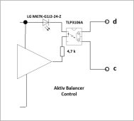
I guess you are looking for a circuit like this one:Does anyone have experience with using a transistor or FET instead of a relay to switch the run port on the balancer? I'm thinking of a small board with e.g. ESP8266 that reads all cell voltages from my BMS via RS485 and switches the balancer on or off depending on the load current and cell voltage.
It is therefore necessary to know the electrical characteristics of the balancer's running connection.
View attachment 131350
Attachments
Hans, did you also look into and could you figure out how to use an optocoupler to switch the active balancer on and off? That would be probably the most neat, efficient, cheap, precise, convenient smart solution of all or?I guess you are looking for a circuit like this one:
Hans Kroeger
New Member
- Joined
- Dec 30, 2020
- Messages
- 128
Yes, you can also use an optocoppler, preferably with a FET output.Hans, did you also look into and could you figure out how to use an optocoupler to switch the active balancer on and off? That would be probably the most neat, efficient, cheap, precise, convenient smart solution of all or?
However, it is more expensive and requires more power.....
I used both types of circuit. I ended up with the simple P-Channel MOS FET transistor in the diagram above, rather than an optocoppler.
Attachments
Many thanks for sharing the diagram!Yes, you can also use an optocoppler, preferably with a FET output.
However, it is more expensive and requires more power.....
I used both types of circuit. I ended up with the simple P-Channel MOS FET transistor in the diagram above, rather than an optocoppler.
Do i understand correctly that your diagram describes how mueller energy modified (active balancer is switched on and off whenever passive balancer is switched on and off) their custom bms? Is the mosfet in your diagram one of the mosfets in the passive balancing circuit?

Similar threads
- Replies
- 4
- Views
- 393
- Replies
- 13
- Views
- 751
- Replies
- 6
- Views
- 391
- Replies
- 1
- Views
- 240
- Replies
- 4
- Views
- 581