diy solar

diy solar

Adding extra solar capacity through hybrid inverter with zero export

Azydo

New Member
Joined
Nov 1, 2023
Messages
24
Location
US
Hello All,
I appreciate any guidance for a novice like myself as I’m trying to add capacity to my solar system. Currently, I have a 4.9 KW solar system using microinverters that is tied to the grid with net metering implemented. My main panel has a 125Amp main breaker. I don’t know what its busbar rating is, since it is somewhat old (house built around 1976) but I assume it is also 125Amp similar to the main breaker. Solar is connected to main panel through a 2P-30amp breaker placed at the bottom of the main panel. I also have a subpanel where a good chunk of my loads is located (pump, EV charger, heater…). The subpanel (main lug load center) has a 125Amp rating and is connected to the main panel through a 2P-60amp breaker located on the opposite side of the 2P-30A breaker used for solar.

I’m trying to add a separate solar system using 10KW Sungoldpower hybrid inverter (SPH10K48SP) along with 2 X 48V 100AH Server Rack Lifepro battery SG48100P that I want to use to add additional solar capacity. My plan is to configure the inverter to zero export to avoid overloading the subpanel.

According to the user manual of the inverter, it requires:
  • 2P-25A breaker for PV input
  • 3P-63A breaker for AC input
  • 3P-63A breaker for AC output
  • 2P-250A for Battery bank

My questions are:
  1. Can I use my existing subpanel to install the 3P-63A breaker needed for the AC inverter input? if yes, do I need to replace the existing 2P-60a breaker that exists in the main panel to control the subpanel?
  2. Would the 3P-63A breaker be used as AC input and output?
  3. Should the 2P-25A breaker be DC rated?
  4. Should any fuse be installed? if yes, what size?
  5. Where should I install the battery 2P-250a breaker?

Thanks for any help!
 
.According to the user manual of the inverter, it requires:
  • 3P-63A breaker for AC input
  • 3P-63A breaker for AC output
Are you sure? Can you post the page that says 3 pole.
 
Zapper, please see pages 12 and 13 of the attached user manual for the inverter.
 

Attachments

  • SPH_split_phase_solar_charger_inverter_user_manual_3.0-20231012.pdf
    2.6 MB · Views: 6
Hello All,
I appreciate any guidance for a novice like myself as I’m trying to add capacity to my solar system. Currently, I have a 4.9 KW solar system using microinverters that is tied to the grid with net metering implemented. My main panel has a 125Amp main breaker. I don’t know what its busbar rating is, since it is somewhat old (house built around 1976) but I assume it is also 125Amp similar to the main breaker. Solar is connected to main panel through a 2P-30amp breaker placed at the bottom of the main panel. I also have a subpanel where a good chunk of my loads is located (pump, EV charger, heater…). The subpanel (main lug load center) has a 125Amp rating and is connected to the main panel through a 2P-60amp breaker located on the opposite side of the 2P-30A breaker used for solar.

I’m trying to add a separate solar system using 10KW Sungoldpower hybrid inverter (SPH10K48SP) along with 2 X 48V 100AH Server Rack Lifepro battery SG48100P that I want to use to add additional solar capacity. My plan is to configure the inverter to zero export to avoid overloading the subpanel.

According to the user manual of the inverter, it requires:
  • 2P-25A breaker for PV input
  • 3P-63A breaker for AC input
  • 3P-63A breaker for AC output
  • 2P-250A for Battery bank

My questions are:
  1. Can I use my existing subpanel to install the 3P-63A breaker needed for the AC inverter input? if yes, do I need to replace the existing 2P-60a breaker that exists in the main panel to control the subpanel?
  2. Would the 3P-63A breaker be used as AC input and output?
  3. Should the 2P-25A breaker be DC rated?
  4. Should any fuse be installed? if yes, what size?
  5. Where should I install the battery 2P-250a breaker?

Thanks for any help!
If it requires a 3 pole breaker, in north america residential, it must require the neutral on a pole.
Perhaps they mean a gfci breaker?
If gfci is what they want, then yes you can use it.
If not, then it is unlikely to work with your existing panel.
Most likely you will need a DIN style breaker and panel.
 
My questions are:
  1. Can I use my existing subpanel to install the 3P-63A breaker needed for the AC inverter input? if yes, do I need to replace the existing 2P-60a breaker that exists in the main panel to control the subpanel?
  2. Would the 3P-63A breaker be used as AC input and output?
  3. Should the 2P-25A breaker be DC rated?
  4. Should any fuse be installed? if yes, what size?
  5. Where should I install the battery 2P-250a breaker?

Thanks for any help!


2. Yes
3. DC rated
4. In the the bussbar for battery ( mrbf) or the battery cable before the 2P-250a braker

You can find fuse size here...

Look at this pic of the breakers...should give you and idea...its an example...you can do it a lot of ways
 

Attachments

  • Screenshot_20230901-014430_Samsung Internet.jpg
    Screenshot_20230901-014430_Samsung Internet.jpg
    903.4 KB · Views: 18
Is neutral switching outside of a 3 pole transfer switch code compliant/advisable in the US?

My current belief is that you should not switch to match domestic convention and protect against one set of failure modes.
 
If it requires a 3 pole breaker, in north america residential, it must require the neutral on a pole.
Perhaps they mean a gfci breaker?
If gfci is what they want, then yes you can use it.
If not, then it is unlikely to work with your existing panel.
Most likely you will need a DIN style breaker and panel.
It looks like the 3P-63 amp indicated in the user manual is for non-US usage. Other forum users have indicated that they used 2P-60 Amp breaker for US 120/240. With that in mind, can I use my existing subpanel for the AC 2P-60 amp breaker for inverter input/output?
 
You can use a regular 60A breaker in the existing subpanel (I assume fed from grid power) for an off grid inverter or for the grid input from a hybrid inverter. The input from a hybrid is bidirectional.

You cannot feed the output from a hybrid or off grid into that panel. In general subpanels should be connected like a branching tree. If you deviate from that you need to ask hard whether it is OK. Most of the time it’s wrong, one time where it works is paralleling inverters.
 
"You cannot feed the output from a hybrid or off grid into that panel."
I plan to configure my hybrid inverter to zero export. Would that work then?
 
"You cannot feed the output from a hybrid or off grid into that panel."
I plan to configure my hybrid inverter to zero export. Would that work then?
The bidirectional AC in is fine. And this will be how the wiring diagram from a properly written manual will show. IOW the grid connection can only be connected to AC in.

If you tie AC out and AC in ports from the inverter to the same panel, then no. Because now AC out touches grid, and that would be rude when the inverter is supposed to be grid forming (ie, it disconnects AC in to prevent forming an uncontrolled island/backfeeding the grid through the bidirectional connection)

Pictures of your wiring ideas would help and I can say which ones are ok/not ok. Unfortunately I don’t have the cycles right now to draw pictures to explain.
 
"IOW the grid connection can only be connected to AC in."

So AC input should be pulled from the main panel (grid) into the inverter while AC output should feed from the inverter into the subpanel. is this understanding correct?
 
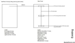
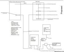
I'm attaching a diagram of the existing and proposed configurations. Basically, moving most of the loads to the subpanel, then adding a 2P-60 amp breaker for AC input to the inverter pulling from the main panel, adding a 2P-60 amp breaker for AC output from inverter feeding the subpanel, added a 40 amp DC disconnect switch between solar panels and inverter, and finally added a 2P-250 amp breaker and 200 amp fuse between the battery bank and inverter. I also indicated the type of wire used.

Would this be a valid/safe configuration? Appreciate any tips.

Capture1.JPG
Capture2.JPG
 

Attachments

  • P1.pdf
    103.8 KB · Views: 3
I’m trying to add a separate solar system using 10KW Sungoldpower hybrid inverter (SPH10K48SP) along with 2 X 48V 100AH Server Rack Lifepro battery SG48100P that I want to use to add additional solar capacity. My plan is to configure the inverter to zero export to avoid overloading the subpanel.

I'm not sure it's code-compliant to use zero export to avoid overload. I vaguely remember there is a provision for that but this is IMO too risky for a beginner project.

Also this isn't a hybrid nor a zero-export setup. It's an off-grid all-in-one. I don't know why SRNE / Sungold called it a hybrid other than to be marketing jackasses. I'm pretty sure this price point of inverter can NOT blend between grid and battery/solar power for the purposes of neither surge rating nor powering continuous loads. (All the blending discussed in the documentation is blending of charge source which is much simpler to implement and fewer regulation problems)

All that said, the subpanel should be fed from the output of the SPH, not the main panel. So delete the top connection labeled AWG#8.

Since this is an off-grid setup, there is no chance of overloading the main panel from backfeed. If it was a real hybrid there would be, and you would also need to consider zero export.

You definitely cannot support all the loads you have listed on that subpanel. Your amp estimates are also wrong or transposed for a lot of the appliances. Maybe there is a way to selectively move some loads over to that subpanel on a seasonal basis. My guess is pulling the EV charger off that and leaving everything else, OR putting the EV charger on there and some small constant loads, would be fine.

6/3 NM is only rated to 55A, you need 6/3 MC, 4/3 NM, or #6 THHN to max out the bypass current.

You can consider going up to 65A (NEC allows rounding up), however you need to make sure the load calculation stays below 63A. The above correct cable/wire types is capable of carrying 65A.
 
All that said, the subpanel should be fed from the output of the SPH, not the main panel.

Thanks for the feedback.

The subpanel is a main lug load center with no main breaker, how to feed it from the inverter output?
 
Thanks for the feedback.

The subpanel is a main lug load center with no main breaker, how to feed it from the inverter output?

Hmm actually it doesn’t really matter which position you feed the busbar from. You already have a breaker in your picture feeding that subpanel.

That breaker will need a hold down kit to be safe.
 
Hmm actually it doesn’t really matter which position you feed the busbar from. You already have a breaker in your picture feeding that subpanel.

That breaker will need a hold down kit to be safe.
How about replacing the existing subpanel with a different one that has a main breaker? I can then use the 2P-60 amp ac output from the inverter as the subpanel main breaker. Would that work? I need a new panel anyway as I'm running out of spaces in the existing one.
 
Sure, subpanels are pretty interchangeable. It's good to keep the same brand though to allow reusing stuff.

How big is the existing subpanel? Can you make space by squeezing in tandem breakers? Probably easiest just to post a photo.
 
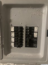
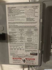
Existing subpanel:

IMG_5062.JPG

IMG_5063.JPG
Sure, subpanels are pretty interchangeable. It's good to keep the same brand though to allow reusing stuff.

How big is the existing subpanel? Can you make space by squeezing in tandem breakers? Probably easiest just to post a photo.

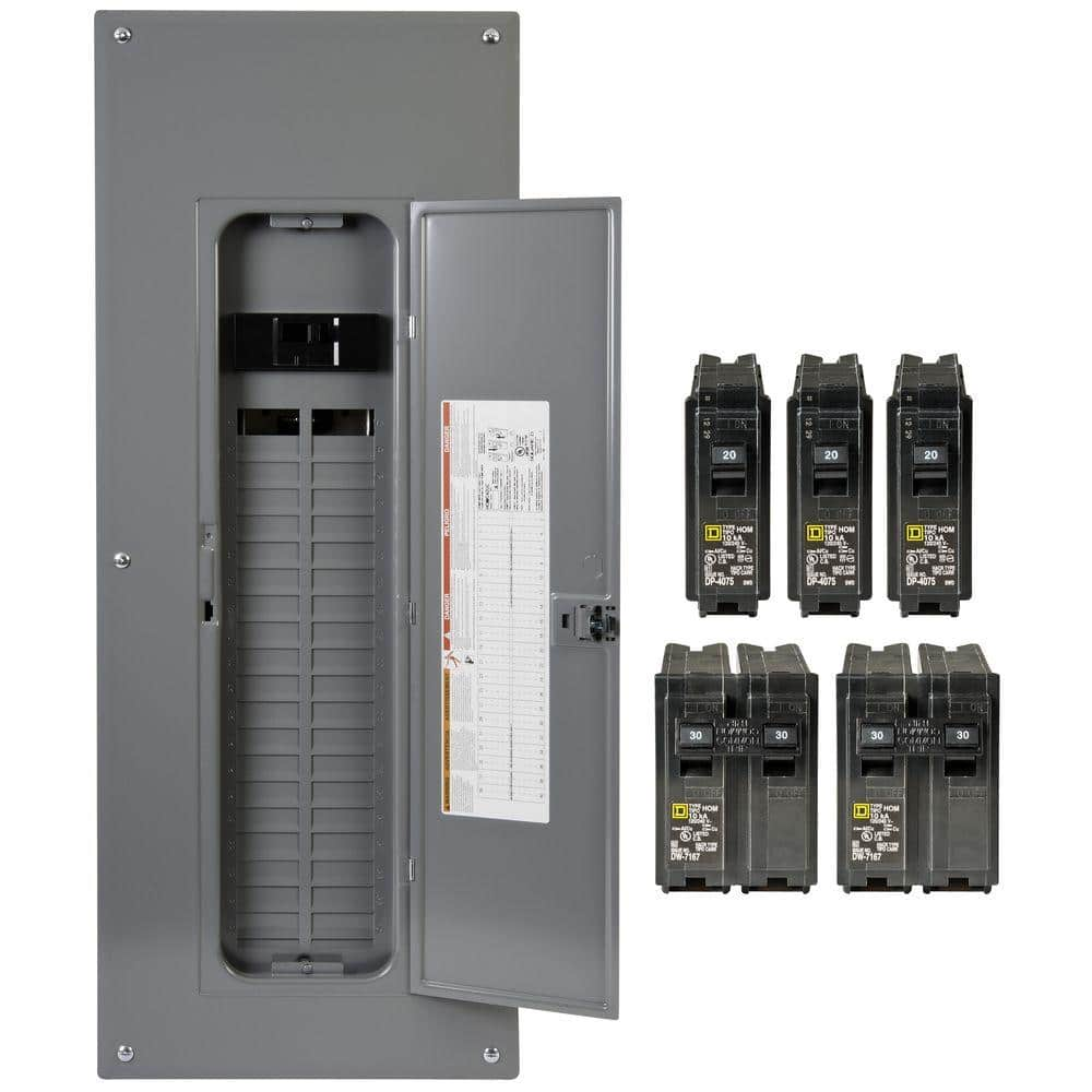
I'm considering this Square D panel as a replacement:
 
Back
Top