diy solar

diy solar

Adding extra solar capacity through hybrid inverter with zero export

Yeah it’s time for a new one. Might want to get a 225A busbar one for a little more flexibility when doing solar. But that could also be overkill for off grid.
 
Yeah it’s time for a new one. Might want to get a 225A busbar one for a little more flexibility when doing solar. But that could also be overkill for off grid.
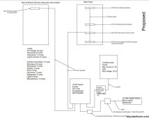
So assuming I use a Square D 225 amp new subpanel, how do I feed the new subpanel with the AC output from the inverter? Do I just replace the main breaker of the subpanel with the 2P-60 amp AC output from the inverter?
 
Already explained above. Remove the main breaker. Backfeed it with a 60A or 65A breaker, screwed down with the hold-down kit & with the terminals covered with the insulation from that kit.

It's probably better to get it with the main breaker so you have one in case you reconfigure it later. Or if you get Main Lug Only make sure it is convertible so you don't have to rip it out if you end up needing a main breaker in a future configuration.

Updated proposed configuration diagram per previous feedback.
  1. Given the new 225 amp subpanel, is it ok to have most of the loads at the subpanel, including the EV charger, as indicated?
  2. Is the 10 AWG ok for the proposed 14 PV solar panels? do I need to go higher (8 AWG) with the wire size?
  3. Can the 2P-65amp ac input for the inverter be installed at any position of the busbar of the main service panel, or does it need to be at upper end as indicated in the diagram?
Thanks,

Capture3.JPG
 

Attachments

  • Capture3.JPG
    Capture3.JPG
    217.1 KB · Views: 0
Given the new 225 amp subpanel, is it ok to have most of the loads at the subpanel, including the EV charger, as indicated?
No, busbar capacity doesn't help with that. It doesn't affect the reasons why I don't think you should put those, as listed in previous post.

What was your reasoning behind how you picked those loads?

Considerations:
  • With this class of inverter if you go over the the ampacity I'm pretty sure if you go over the 10kW capacity of the inverter the whole load will transfer back to grid. Tag one of the build threads on SRNE10K to see what the people that have this inverter know about the behavior.
    • IE 10kW - 240*32 = 2.4kW left for your other loads. It just takes microwave and dishwasher running at the same time to knock it off
    • Is that a 120V heat pump dryer? 5A is very weird for a 240V dryer, kind of high for a heat pump dryer and super low for a standard dryer
    • If you want to try to avoid going over 10kW you can install a load managed EVSE like Emporia or Wallbox that cuts the draw on EVSE if total load goes over 10kW. Then it's likely that everything on that subpanel will fit. But not guaranteed. I'd pick the Emporia since it's more beginner friendly unless you have experience integrating the extra DIN and communications wiring needed for Wallbox.
  • With the rate of progress in this thread, I feel like you have a higher chance of needing to revisit decisions. So you need to configure your setup to be easy to swap individual circuits between grid and inverter power.
  1. Is the 10 AWG ok for the proposed 14 PV solar panels? do I need to go higher (8 AWG) with the wire size?
No problem to go with #10, in fact it's way over what is needed, but it is good to use #10 to get some level of future proofing. Though if you want to consider going to 2P config (not sure if supported by MPPT) #10 is not enough to carry it. So you're not getting much future proofing for #10 as compared to different panels with lower ampacity. #8 would be enough to carry 2P of those panels.

You sure that Dihool disconnect is NRTL listed? Does it have special feature like metal case (needed inside building). Which the go-to type (IMO brand) typically does not have.

You sure those battery fuses are the recommended type on this forum? Same with breaker.

(I don't know anything about battery fuses other than to parrot what people use, I would recommend you search for that from reputable members).

Battery fuses and breakers are not places to go shopping for yourself.
  1. Can the 2P-65amp ac input for the inverter be installed at any position of the busbar of the main service panel, or does it need to be at upper end as indicated in the diagram?
Any position is fine. I usually backfeed at the top to keep things organized.

Have you considered hiring out to Greenlancer for your final drawings for permitting?
 
Last edited:
No, busbar capacity doesn't help with that. It doesn't affect the reasons why I don't think you should put those, as listed in previous post.
Ok. As you previously suggested, I think I'll move the EV charger from the subpanel to the main service panel while keeping the rest of the loads on the subpanel.

You sure that Dihool disconnect is NRTL listed? Does it have special feature like metal case (needed inside building). Which the go-to type (IMO brand) typically does not have.
Well, this was suggested by another member who has the same inverter.

Have you considered hiring out to Greenlancer for your final drawings for permitting?
Looking into it, Just trying to sort out material and things that I can do myself from what needs a professional to be done.
 
Ok. As you previously suggested, I think I'll move the EV charger from the subpanel to the main service panel while keeping the rest of the loads on the subpanel.

That's the easiest way to do this. Keep the idea of installing the load managed EV charger in mind too, that might be a good way to max out your benefit from this system. EG if you can't use up the batteries completely every day.

Well, this was suggested by another member who has the same inverter.

Ah that one. Yeah that member seems pretty on top of things, and I saw this specific Dihool on that thread. It looks decent (famous last words) and I like the clean integration with SPD. I don't see any US safety markings though.

Don't rely on this as a breaker (just a disconnect switch) and it's probably OK.

The direct easy fully code compliant competitor (IE you buy a package, it's all good, but you pay more for it) would be a midnite combiner box + breakers it comes with + SPD combination, but that's probably 2x more expensive.

IMO would be cheaper but does not have an integrated SPD in most models.

Looking into it, Just trying to sort out material and things that I can do myself from what needs a professional to be done.
I don't think your equipment choice would be eligible for permits (inverter and battery) so the planset would be to make sure you have some closely vetted and cleanly specified plans to follow.
 
Another thing you can do to prepare is install energy monitor on the circuits you're thinking of moving to the off-grid AIO.

And then watch the usage for a few weeks (NEC says 30 days is good). You can then see what the peak power is as well as daily energy draw.

(of course correct by situations like AC not running during the 30 days, and adding that in manually)
 
I don't think your equipment choice would be eligible for permits (inverter and battery) so the planset would be to make sure you have some closely vetted and cleanly specified plans to follow.
Do you know where or who can provide help with preparing such plans?
 
The existing solar system is grounded to a ufer in my house through #8 AWG. Do I need to implement a separate grounding to the proposed solar?

Thank you for your patience with my questions.
 
I use Square D QO panels from Schneider.
Busbar ratings vary. I've got some rated 200A, some 225A. Smaller ones are 125A or 150A. I think Homeline is up to 200A.
They do sell panels with 150A or other main breakers; you have to make sure you get the busbar rating you want. Also main lug only panels (in which case busbar rating will be clearly identified.)

If you want interlock/bypass for grid or generator, use a main breaker plus backfed branch circuit breaker.
QO series, you can interlock up to 125A branch breaker. Homeline series, there is a 200A breaker which I think will interlock. It may be meant for use as a main breaker mounted at center of busbars, but it looks to me like it can work as branch breaker too.

Of course you have to manage loads within inverter capacity, and available charge on battery. My inverter has controls based on SoC and derating of output. I'd expect load cycling if enabled/disabled based on derating (maybe with a slow thermal time-constant.) Does your SunGoldPower offer any load management?
 
The existing solar system is grounded to a ufer in my house through #8 AWG. Do I need to implement a separate grounding to the proposed solar?

Thank you for your patience with my questions.
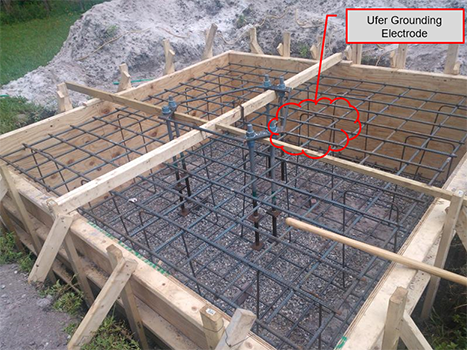
Im not sure what an ufer is, but if you have all the solar components connected to the grounding system in the house, you are good to go.
 
Just the most effective grounding scheme known to man.
I think it could be a loop of wire in base of concrete perimeter foundation, but usually the rebar itself.


So would it be safe to ground the proposed system to the ground bar in the main service panel, since this main panel itself is grounded to the Ufer?
 
I would connect inverter chassis ground back to main panel ground. With a green or bare wire that runs together with AC line and neutral feeding inverter from main panel.

I would ground PV panel frames back to inverter chassis ground. NOT directly back to main service panel. It should follow PV+/PV- wires back to inverter. Don't want DC leakage current going through a wire that carries AC ground, if a cable is opened for electrical work, that would interrupt the grounding of panel frames.
 
It shuts itself off for overheat or other overload.

You could enable/disable loads based on voltage or an Ah meter, make use of available power when battery full, and shut off big loads to keep others operating when battery is low.

You could enable a dump load like water heater when voltage gets up into knee of curve. That could interfere with good cell balancing, although once water is hot and thermostat shuts off, it would let charging finish.

At low voltage disconnect of inverter, you could have a second small inverter power critical loads. What I use is a load-shed relay that disconnects all loads (could keep critical connected.)

You might want to run an A/C, but only when a well pump isn't running. Easiest way to do that would be well pump circuit opens thermostat.
Another way to regulate max load would be CT measuring inverter output, enabling or disabling optional load.
 
PV should go back to inverter for consistency. because code requires the EGC to go same path as the circuit it protects, & because some safety equipment requires the EGC from the solar components to be present at the inverter.

Though PV EGC does have special dispensation to take an alternate route IIRC (as long as it ends up in the right place). Whether it's worth leveraging this dispensation is complicated I guess.
 
Back
Top