Q-Dog
¯\_(ツ)_/¯
That's when I get the vendor on the phone.I can almost quote mine, never mentions what to do if your unit skips setting 24?


That's when I get the vendor on the phone.I can almost quote mine, never mentions what to do if your unit skips setting 24?
That's when I get the vendor on the phone.
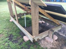
I love that mounting system is simple yet ingenious. What is the degrees of the angles of the 2 positions?
The only Problem I see is you need something between the wood and the ground. Like a paver or gravel or some type of hard plastic, that will keep the word from rotting as fast. Also is the 4x4 in the ground or in cement? If its in the ground it will rot out fast, it needs to be in cement with a gravel at the bottom of the hole.
Good just remove any dirt from around the 6x6 post and put gravel there. That way grass will not grow right next to the post and bring with it water that will rot the post out.Thanks, at level the array sits at 34 degrees, which is my lat. Tilts forward and back 15 degrees.
Using pavers to adjust angle, and will put some pea gravel down for ground contact. The 6x6 posts are in concrete.
The 70 Degree app makes setting angles a breeze.
I can answer some questions about how the Growatt handles ground and neutral bonding. Short version: it doesn't.
Long version: I have the 3000w Growatt (SPF 3000TL LVM-48P) and have stumbled upon some neutral and ground issues while testing mine. I'm just going to brain dump my observations and measurements:
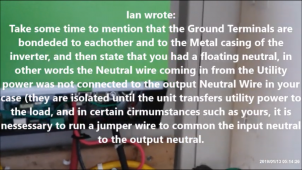
1. The ground terminals of AC input and AC output are connected (bonded) to each other and the metal chassis at all times. This is true even with the Growatt completely unpowered and disconnected.
2. The neutral terminals of the AC input and AC output are never connected (bonded), regardless of connections, operation mode, and settings.
3. The AC output neutral and AC output ground are never bonded internally by the Growatt. When AC input is grid connected and running in bypass mode, the AC output neutral and ground are technically bonded, because they are bonded at the utility service panel. In any mode where the inverter is powering the load, neutral is not bonded to ground.
4. The dry contacts (and associated setting 24) can be utilized to trigger an external grounding box - basically, a relay switch that bonds ground and neutral. The manual is extremely vague about this.
5. Unless you have externally bonded AC output neutral to ground, the neutral line will have a floating voltage ~60V N-G. (H-G = 60V, H-N = 120V)
As I understand it (disclaimer: I am not an electrician) the US NEC requires that neutral and ground are bonded only at the first service panel. I know these Growatt (and similar - MPPT, etc) are marketed as "Off Grid" even though utility charging/bypass is a prominent feature, but that leaves you to figure out bonding.
Practically speaking - if you are going to use the inverter as portable (like that hand truck I saw posted) then it is not going to be properly grounded anyway. If this is going into a dwelling where it will run unattended, then there are some safety issues that should be addressed first.
getalab,
Are you using one of those 3-neon bulb circuit testers? The result was ambiguous on mine - one of the bulbs was half-bright because of the floating neutral. A voltage meter was much more useful for verification.
Here is what I did temporarily while troubleshooting. First, I tested the outlet supplying grid power to the Growatt input. Make certain it has a good ground, and no voltage between neutral and ground pins. If that is good, then fully shut down and disconnect the Growatt inverter. Using a short piece of insulated wire, connect N terminals of AC input and output together. Then reconnect everything else and retest. Don't worry about setting 24 for this test. If the problem goes away while the AC input is connected to a good grid-fed receptacle (even when running on inverter mode) then the missing neutral-ground bond is the root cause. Only attempt this if you understand and are comfortable doing this test yourself. Also, don't use this as a permanent solution.
My use will be a permanent style setup, using now in my house,and plan to transfer it to rv in future.
Test light is the three neon bulbs, and mine are bright. I’ve watched it switch from utility to battery, and fault light goes off immediately.
Thanks for the reply, very informative. I don’t want to try anything until I hear from Signature Solar, but the fix you mentioned makes sense.
I hope you get it figured out. I have my Victron grounded on the AC side and I tested it to make sure it all works properly when switching from grid to inverter. Haven't done anything about grounding the DC side because some of my setup is still temporary.
I suspect a lot of people ignore the gounding issue. I am not comfortable with that, especially since others in the house might need to deal with my system when I am gone.
You are probably right. Your setup will run loads without issue, and most people will not notice or perform additional AC tests. Since bought 2 of these inverters to do split-phase in a house, to feed a separate load center, I wanted to make certain I understood the capabilities and shortcomings of these units. When I found the floating neutral during testing of a single Growatt unit, I did a ton of searching on the forums here and beyond. Except for people copy-pasting the text from the manual (setting 24) I have not seen any install details, such as grounding box.I pretty much followed the basic “all in one” setup, so I assume some must have issues and not know it, since everything seems to work fine.
Just tested my AC with multimeter, and got 63V at ground.
Tried running a ground wire from GW to utility ground, and that didn’t change anything.
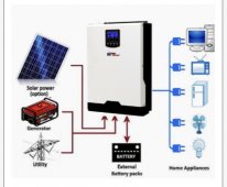
What is a basic "all in one" setup?
What is a basic "all in one" setup?
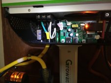
 I did a quick scan and didn't see any mention of grounding in there.
I can answer some questions about how the Growatt handles ground and neutral bonding. Short version: it doesn't.
Long version: I have the 3000w Growatt (SPF 3000TL LVM-48P) and have stumbled upon some neutral and ground issues while testing mine. I'm just going to brain dump my observations and measurements:
1. The ground terminals of AC input and AC output are connected (bonded) to each other and the metal chassis at all times. This is true even with the Growatt completely unpowered and disconnected.
2. The neutral terminals of the AC input and AC output are never connected (bonded), regardless of connections, operation mode, and settings.
3. The AC output neutral and AC output ground are never bonded internally by the Growatt. When AC input is grid connected and running in bypass mode, the AC output neutral and ground are technically bonded, because they are bonded at the utility service panel. In any mode where the inverter is powering the load, neutral is not bonded to ground.
4. The dry contacts (and associated setting 24) can be utilized to trigger an external grounding box - basically, a relay switch that bonds ground and neutral. The manual is extremely vague about this.
5. Unless you have externally bonded AC output neutral to ground, the neutral line will have a floating voltage ~60V N-G. (H-G = 60V, H-N = 120V)
As I understand it (disclaimer: I am not an electrician) the US NEC requires that neutral and ground are bonded only at the first service panel. I know these Growatt (and similar - MPPT, etc) are marketed as "Off Grid" even though utility charging/bypass is a prominent feature, but that leaves you to figure out bonding.
Practically speaking - if you are going to use the inverter as portable (like that hand truck I saw posted) then it is not going to be properly grounded anyway. If this is going into a dwelling where it will run unattended, then there are some safety issues that should be addressed first.
getalab,
Are you using one of those 3-neon bulb circuit testers? The result was ambiguous on mine - one of the bulbs was half-bright because of the floating neutral. A voltage meter was much more useful for verification.
Here is what I did temporarily while troubleshooting. First, I tested the outlet supplying grid power to the Growatt input. Make certain it has a good ground, and no voltage between neutral and ground pins. If that is good, then fully shut down and disconnect the Growatt inverter. Using a short piece of insulated wire, connect N terminals of AC input and output together. Then reconnect everything else and retest. Don't worry about setting 24 for this test. If the problem goes away while the AC input is connected to a good grid-fed receptacle (even when running on inverter mode) then the missing neutral-ground bond is the root cause. Only attempt this if you understand and are comfortable doing this test yourself. Also, don't use this as a permanent solution.
@fazeshift..using a multi, I’m getting 62v floating as you calculated.
Assuming the jumper wire trick you mentioned worked in my case, what would be the permanent fix for this? Any ideas?
Seems the jumper between neutrals is what watts 24/7 suggests on their MPP units, and he seems to be familiar with the issue.

 diysolarforum.com
Did you see the discussion in this older thread...
MPP Solar LV5048 Bonding & Grounding question.
I'm working on slow install of my LV-5048 and I had a question and a crude diagram of my question. 1. Do I bond my Neutral and Ground on the critical loads panel? 2. Should I run a ground wire from my main service panel to my Critical loads panel grounding bar? Im not sure how MPP solar...
diysolarforum.com