diy solar

diy solar

MPP Solar LV5048 Bonding & Grounding question.

SolarBro

Solar Budgeteer
Joined
Jun 27, 2020
Messages
91
I'm working on slow install of my LV-5048 and I had a question and a crude diagram of my question.

1. Do I bond my Neutral and Ground on the critical loads panel?

2. Should I run a ground wire from my main service panel to my Critical loads panel grounding bar?

Im not sure how MPP solar handles grounding internally in the unit. So I wanted to know who has worked with MPP units to handing where they bond G/N together if they are also receiving grid inputs and not purely off-grid.

Thank you!
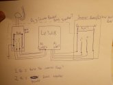
20200627_213725.jpg
 
1. No
2. Yes

You never want to bond the neutral and ground in a sub panel (counting the inverter as a main panel) because you don't want current on the ground wire. I can't say for sure, but I would think the ground and neutral would be bonded in the inverter already. You could check this with a continuity test.
 
I can't say for sure, but I would think the ground and neutral would be bonded in the inverter already.
IMO, a poor assumption to make on a non-UL rated device.

From the manual- 4 hits/2 details on grounding/bonding using a word search:

11. GROUNDING INSTRUCTIONS -This inverter/charger should be connected to a permanent grounded wiring system. Be sure to comply with local requirements and regulation to install this inverter

AC Input/output Connection: Please follow below steps to implement AC input/output connection:
1. Before making AC input/output connection, be sure to open DC protector or disconnector first.
2. Remove insulation sleeve 10mm from the six conductors. And short-circuit phase L and neutral conductor N 3 mm.
3. Insert AC input wires according to polarities indicated on terminal block and tighten the terminal screws. Be sure to connect PE protective conductor ( ) first. → Ground (yellow-green) L1→ LINE (black) L2→ LINE (brown) N→ Neutral (blue)

Agree with above -The critical load panel as displayed is a subpanel in your system.

Ground connection is part of the AC input/output connection.

Equipment bonding is not detailed. Is there a bonding lug on the LV5048 -seperate from the AC connection?
 
Thank you both.

-Ill run a ground wire to the main panel ground bus bar (which has my grounding rod) to my critical loads ground bar.

-Do NOT bond the critical loads panel.

Ill post back when im getting to that stage of the build. Still running my underground stuff. :)
 
Thank you both.

-Ill run a ground wire to the main panel ground bus bar (which has my grounding rod) to my critical loads ground bar.

-Do NOT bond the critical loads panel.

Ill post back when im getting to that stage of the build. Still running my underground stuff. :)
If I were you I would just use the same ground wire for your AC INPUT and OUTPUT connections as your bonding wire. Just bridge the ground input and output in the inverter so you have a solid ground from your main panel to your subpanel (once again I would assume the grounds would be bridged internally but you can confirm this with a continuity test).
 
@Supervstech -opinion on the bonding method below.

If I were you I would just use the same ground wire for your AC INPUT and OUTPUT connections as your bonding wire. Just bridge the ground input and output in the inverter so you have a solid ground from your main panel to your subpanel (once again I would assume the grounds would be bridged internally but you can confirm this with a continuity test).
 
If I were you I would just use the same ground wire for your AC INPUT and OUTPUT connections as your bonding wire. Just bridge the ground input and output in the inverter so you have a solid ground from your main panel to your subpanel (once again I would assume the grounds would be bridged internally but you can confirm this with a continuity test).
The panels are right next to each other, itd be simple to ground them together.

Ill check continuity in the inverter just incase.
 
I would test the unit with a voltmeter to figure it out. I just installed the lv2424 hybrid (in an off grid application) and the unit does not have an internally bonded neutral. In that unit the AC input and output grounds are connected (resistance test). In my off-grid application I bonded the neutral to ground in the main service panel that the AIO only feeds.

Just be aware that if you use transfer switches it may close a connection to the main service panel and therefore remove your neutral bond
I tested mine as well and was surprised to find that there was no neutral - ground bond internally in the inverter. So to alleviate this I simply put a jumper between the neutral and ground on the AC OUT. It seems to have alleviated my issues because I now have 120v to ground whereas before I only had 66.
 
I tested mine as well and was surprised to find that there was no neutral - ground bond internally in the inverter. So to alleviate this I simply put a jumper between the neutral and ground on the AC OUT. It seems to have alleviated my issues because I now have 120v to ground whereas before I only had 66.

Do you have a photo of how you did this? So I should do this in the inverter and NOT in the critical load panel?
 
I don't know the answer to your question. But my question would be: if you bond the neutral at the main service panel, and you have line power, everything should work because the subpanel neutral is connected to ground (through the inverter) at the main service panel. But, if the line power goes down, does the relay in the inverter disconnect the the line power input neutral/l1/l2 and therefore disconnect your subpanel neutral ground bond at the main panel.

Every thing i have read says you must only have one bonded neutral location " Another issue that can occur, is that multiple (and illegal) neutral-to-ground bonds can exist in the system (only one bond is allowed in the main panel). When this occurs, both the ground and the neutral become current-carrying conductors, which effectively means that you have two (2) neutral wires running in parallel. This divides the current and places electrical energy on to the chassis of all metallic objects within the system. Another hazardous situation. " https://www.esgroundingsolutions.com/why-do-you-have-to-bond-the-neutral-and-the-ground-wire-in-the-main-panel/

Sorry I do not know the answer
 
Do you have a photo of how you did this? So I should do this in the inverter and NOT in the critical load panel?
These inverters are weird. Do not bond the neutral and ground in the critical loads panel because you will get current back on your ground wire to the inverter. If you bond the neutral and ground at the inverter (which is what I did) it will work fine while it's in battery /solar mode, but if it kicks into bypass mode, you will have current on your ground wire back to your main panel. My idea now is to put a jumper between the AC IN neutral and the AC out neutral. That way you would have a neutral ground bond in your main panel, without carrying current on your ground wire. I'm tinkering with mine as well right now so I'll let you know what works.
 
I don't know the answer to your question. But my question would be: if you bond the neutral at the main service panel, and you have line power, everything should work because the subpanel neutral is connected to ground (through the inverter) at the main service panel. But, if the line power goes down, does the relay in the inverter disconnect the the line power input neutral/l1/l2 and therefore disconnect your subpanel neutral ground bond at the main panel.

Every thing i have read says you must only have one bonded neutral location " Another issue that can occur, is that multiple (and illegal) neutral-to-ground bonds can exist in the system (only one bond is allowed in the main panel). When this occurs, both the ground and the neutral become current-carrying conductors, which effectively means that you have two (2) neutral wires running in parallel. This divides the current and places electrical energy on to the chassis of all metallic objects within the system. Another hazardous situation. " https://www.esgroundingsolutions.com/why-do-you-have-to-bond-the-neutral-and-the-ground-wire-in-the-main-panel/

Sorry I do not know the answer
Yes, it disconnects the neutral. As far as I know, there shouldn't be any reason the neutral in and out can't be jumpered to prevent this though.
 
This video link kinda explains it for another system. But I don't know if this unit has the bonded neutral relay ( I don't think it does?). If anything you could make one by using the dry contacts of the unit connected to a relay that connects/disconnects the ground and neutral after the mpp unit. So when connected to the grid the relay is open and the ground-neutral is at the main/service panel. But when power goes down, the relay closes and connects neutral and ground after the mpp unit/subpanel. When grid power comes back the relay opens again and switches neutral ground connection back to the main panel.

Another way would be to use a contactor as discussed here
 
Last edited:
These inverters are weird. Do not bond the neutral and ground in the critical loads panel because you will get current back on your ground wire to the inverter. If you bond the neutral and ground at the inverter (which is what I did) it will work fine while it's in battery /solar mode, but if it kicks into bypass mode, you will have current on your ground wire back to your main panel. My idea now is to put a jumper between the AC IN neutral and the AC out neutral. That way you would have a neutral ground bond in your main panel, without carrying current on your ground wire. I'm tinkering with mine as well right now so I'll let you know what works.

So how did that work out on your unit? Did you just jumper the neutrals from the AC Input and Outputs?
 
I'm putting in a bunch of pip-1012s in my logging cabins. They have grid service so I'm connecting a120v service to the pips.

These Pips will have a subpanel off them to feed the cabin. I have not bonded the neutral and ground in this subpanel. Everything is isolated from grid except that 120v AC input.

This jumper you guys talked about. It was agreed to jumper the neutrals on AC input and AC output on the PIPs. Does anyone have a picture of this.

Just want to see it. I hope this is not too much to ask. I've got some 12/2 to do this.

Thanks in advance

20200728_090937.jpg
 
Thanks SolarBro.

I was wondering if this would smoke the inverter but obviously not when it went off grid and went to solar.

Does your AC OUT go to loads (sub)panel. and does your loads panel have its own earth ground or did you just tie into the grid service ground bar?
Our camps have their own 60 amp grid panel installed. Really basic and old. Never upgraded to to 100 amp because the loads are light in these camps. But the camps use alot of power over the year and a small solar will cut the operating costs down over the decade. I had solar in for years but its ancient and needs upgrading.

I'm just going to use a 15-20amp 120v service to feed the 1012LV's.
I appreciate your picture.
Thanks
 
Back
Top