diy solar

diy solar

EG4 6000XP Neutral-Ground Bonding

Unfortunately, I do not have documentation on this and will reach out on getting this made. However, it is what we found from testing. I would recommend following NEC Article 690.47 in the meantime or reaching out to a local electrician/solar installer.
 
Unfortunately, I do not have documentation on this and will reach out on getting this made. However, it is what we found from testing. I would recommend following NEC Article 690.47 in the meantime or reaching out to a local electrician/solar installer.
Let's be real here... Some DIY folks aren't looking to consult with electrician/solar installer - this is a DIY solar forum.
 
Last edited:
Unfortunately, I do not have documentation on this and will reach out on getting this made. However, it is what we found from testing.

What did you find?

I would recommend following NEC Article 690.47 in the meantime or reaching out to a local electrician/solar installer.

And where does it say in there not to use a common busbar of the AC grounded system? And yes, I also went to 690.41(A)(5).
 
It is not recommended to ground the AC and DC grounds at the PE Bus [sic] of the inverter.

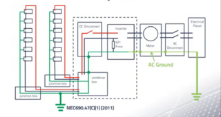
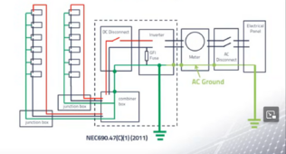
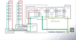
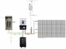
Spoke to electrician (granted not adept in solar) but he was left scratching his head on this one too. Electrical diagrams below comport with NEC Article 690.47.

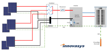
PV Electrical Diagram:

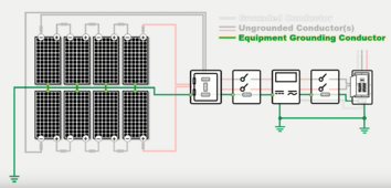
Another PV Electrical Diagram (Pages 6-7 & 11-12):
Another PV Electric Diagram:

Am I missing something here?
 
Last edited:
It is not recommended to ground the AC and DC grounds at the PE Bus [sic] of the inverter.
Doesn't this violate NEC Article 690.47? Totally need clarification...
Unfortunately, I do not have documentation on this and will reach out on getting this made. However, it is what we found from testing. I would recommend following NEC Article 690.47 in the meantime or reaching out to a local electrician/solar installer.
Spells out NEC Article 690.47

More in-depth...

Read through the EG4 6000XP manual several times now and not much details on this topic in general aside from this (PV Input):
EG4-6000XP - PV .pdf.png

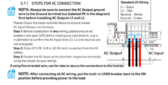
And this (AC Connection):

EG4-6000XP - AC.pdf.png
 
Last edited:
Crickets....
Any grounding busbar should be at zero voltage potential. If during their testing they found an issue (such as voltage on the chassis), they should have been looking for a parallel path.

The purpose of the grounding system is to provide a low impedance path back to source. This enables clearing of a ground fault to trip the breaker or fuse. That is why anything that can conduct power is bonded to the grounding system.

I don't know if the MPPT's on the 6000XP are isolated or not, my guess is probably not. There is always the possibility of a loop if the MPPT's are not isolated. That would be my only thought of a possible problem.
 
From the 3 examples provided above, I do not see how one follows NEC 690.47 without DC-AC grounding at inverter... Simply saying to not ground AC-DC at inverter makes no sense and I think warrants thorough explanation as to why this should not take place.

Info pulled from:
 
Last edited:
They want the main grounding bus bar to be outside of the inverter.
Let's assume that is the case. How does that change that the AC-DC will then be grounded at the inverter? I don't understand how adding a separate bus bar changes anything. I wish we could get a basic wiring diagram that explains this a bit more. I am now on the fence with the EG4 6000XPs and likely just upgrading my old Victrons with newer Victrons.
 
Let's assume that is the case. How does that change that the AC-DC will then be grounded at the inverter? I don't understand how adding a separate bus bar changes anything. I wish we could get a basic wiring diagram that explains this a bit more. I am now on the fence with the EG4 6000XPs and likely just upgrading my old Victrons with newer Victrons.
I’m getting confused reading this. Is someone saying that DC Ground (chassis of batteries or frames of PV) can’t be in the EG4 ground bar? If someone is saying that it makes no sense.
 
I’m getting confused reading this. Is someone saying that DC Ground (chassis of batteries or frames of PV) can’t be in the EG4 ground bar? If someone is saying that it makes no sense.
Check out post #57 & #61.

I think the suggestion may actual be very dangerous.... Hell would even say could kill someone after looking into the importance of connecting all parts through the EGC.

Even with the inverter's internal bond disabled & N-G bond at the breaker panel don't see how one could separate DC and AC. Would love to know why the suggestion was made and maybe some details would be great especially since it came from a person with "EGC online support."

EGC.png
 

Attachments

  • EGC .png
    EGC .png
    495.6 KB · Views: 0
Ah how I've missed these G/N Bond discussions... ?

Since the G/N bond in in the inverter is controlled by a relay, couldn't LuxPower add a 3rd option for the G/N controls which would make it more of a "dynamic" relay (similar to what the 6500s did by default). When AC In/bypass is used, the G/N bond is disabled and when in battery mode it's enabled? It seems like this inverter should be smart enough to be able to do this assuming it's programmed properly.

So you would have "Always On", "Always Off" or "Dynamic".
That's a good idea and "maybe" have it controlled by AI based on prior history of previous use and have an always ask, ask only this time, or never ask again type check box something that could always be changed in the system settings regardless, but similar to say Microsoft 🪟? My question here is is this g/n bond an issue with the eg4 3kw off grid inverter? Bc I am seriously about to purchase 2 of them like tonight maybe in a couple of hours when I work up the courage to spend 10 grand on a complete system overhaul ...
 
Ah how I've missed these G/N Bond discussions... ?

Since the G/N bond in in the inverter is controlled by a relay, couldn't LuxPower add a 3rd option for the G/N controls which would make it more of a "dynamic" relay (similar to what the 6500s did by default). When AC In/bypass is used, the G/N bond is disabled and when in battery mode it's enabled? It seems like this inverter should be smart enough to be able to do this assuming it's programmed properly.

So you would have "Always On", "Always Off" or "Dynamic".
It is not as simple as it sounds. The 6000XP is a common neutral architecture. In order to do dynamic bonding one of two things would be needed:

1) Whenever the the inverter closes the bonding relay it must disconnect input neutral from output neutral. Currently, the 6000XP has both input and output ground on the same busbar so this would be a significant structural change to the design.
2)Detect if there is already an N-G bond in the system and only add one if there isn't. (This would be difficult to implement for all corner cases.)

If the inverter did not do one of the above, it could easily create two NG bonds and that is also problematic.
 
I’m getting confused reading this. Is someone saying that DC Ground (chassis of batteries or frames of PV) can’t be in the EG4 ground bar? If someone is saying that it makes no sense.
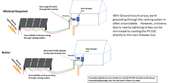
I am not sure what others have said (or not), but I will throw in potential reasons NOT to rout the PV frame ground into the inverter.

I have not personally observed it but there are reports on multiple inverters (multiple different brands) that Routing the PV EGC into the inverter can cause or aggravate LED flickering problems on the AC output. I certainly can not explain why this would be true, but I can believe that it could happen. The PV lines are not isolated from the internal busses and we know many of the all-in-ones have an AC imposed on the input posts of the PV. It is easy to believe the PV power lines have a capacitive or inductive coupling to the ground wire so it is not out of the realm of possibility that there could be issues.... particularly if the PV is a long way from the inverter.

The other reason not to run the PV EGC into the inverter is to avoid picking up ground wave pulses from a nearby lightning strike.

1711930956537.png
 
Last edited:
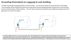
Note that the above issue is very similar to the issues around the requirement of gronding electrodes at seperate buildings:

1711931264350.png
 
What did you find?


And where does it say in there not to use a common busbar of the AC grounded system? And yes, I also went to 690.41(A)(5).
So, we had seen some issues with flickering lights when tying DC grounds onto the PE Bus of the XP.

I will have to look further into this to see why that is, as I don't have conclusive reasoning for it at this time.
 
Back
Top