You are using an out of date browser. It may not display this or other websites correctly.
You should upgrade or use an alternative browser.
You should upgrade or use an alternative browser.
EG4 6000XP Neutral-Ground Bonding
- Thread starter HighTechLab
- Start date
FilterGuy
Solar Engineering Consultant - EG4 and Consumers
HighCountry
New Member
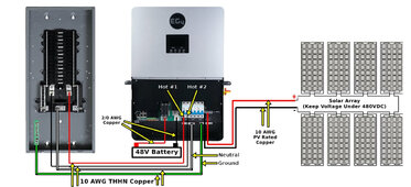
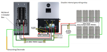
Agree bonding should be in breaker panel not internally. EG4 6000XP default setting internal bonding is enabled, thus need to change setting 26 to disabled.
The panels are built on wood adjustable mounts exactly like this:
Panels are ground from unistrut to unistrut then to breaker. Assume that's fine? Or best to go panel to panel as you illustrated? Also, we installed a grounding rod at the solar panel location - needed?Note that the grounding on the frames of the panels will depend on the mounting system.
The panels are built on wood adjustable mounts exactly like this:
Last edited:
FilterGuy
Solar Engineering Consultant - EG4 and Consumers
The anodization and aluminum oxide are both insulators so the set-up with the washers holding the panels down may not have good electrical contact with the frames. If the grounding is to be to code there should be a commercial grounding lug bolted to each panel and a single wire going from lug to lug.Panels are ground from unistrut to unistrut then to breaker. Assume that's fine? Or best to go panel to panel as you illustrated?
Actually, that is allowed, but not recommended. I would even say it is discouraged.Also, we installed a grounding rod at the solar panel location - needed?
The grounding wire that connects the strut and panels together should be run back to the same grounding system of the house.
When there are two ground rods it can actually cause problems rather than solve problems.
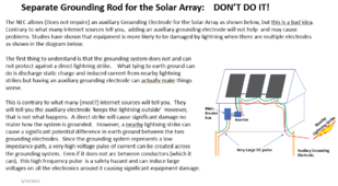
You may want to review this resource:

Grounding Made simpler - Part 3: Solar Panels
To get the paper, click on the orange button at the top of the screen. The subject of grounding is a complex, multifaceted subject, that is often treated as an after-thought but needs to be considered from the beginning of the design and build...
Zwy
Solar Wizard
Earth grounded is not N-G bonded, so some clarification is needed.Read through Filter Guy's paper... Still a bit confused here as it relates to the EG4 6000XP.
I contacted EG4 directly and they replied: "the inverter housing itself doesn't need to be grounded, but there is a ground bus bar in the cabinet labeled PE. That's going to be for your A/C inputs/Output like your GEN/GRID/LOAD Input/Output locations. Each one of those connections made will need four wires L1, L2, a Neutral, and a Ground." And that, "if you do not ground the inverter, that the ground should be made at your load panel, and then connected to the ground bus in your inverter."
This being said, let's say that the main breaker panel is earth grounded (then ground to inverter from panel)
Ground electrode driven at main panel and bond N-G at that panel is what is referred to when N-G bonding in a stationary application. If a rod is driven into earth at that panel without any connection between N and G, then the panel is just earthed and not bonded.
Disable internal bonding. You have the ground electrode at the main panel, this is where you should also bond N-G.what should the setting for the EG4 6000XP internal bonding be - Enabled or disabled? My thought - it should be enabled and the panel not bond at N-G.
Internal N-G bond in this inverter is for a mobile application that would never be plugged into shore power and would not have a ground electrode.
Zwy
Solar Wizard
If N-G bond is in the main panel, then the generator should be unbonded.Ok. Which is the preferred method? Let's assume in future that a generator is added (non N-G bond) would it matter where the bond takes place?
View attachment 202251
Zwy
Solar Wizard
The panel clamps you are using are not rated for bonding purposes. You would need to use clamps that have a point that dig into the frame thru the anodizing.Agree bonding should be in breaker panel not internally. EG4 6000XP default setting internal bonding is enabled, thus need to change setting 26 to disabled.
Panels are ground from unistrut to unistrut then to breaker. Assume that's fine? Or best to go panel to panel as you illustrated? Also, we installed a grounding rod at the solar panel location - needed?
The panels are built on wood adjustable mounts exactly like this:
My clamps do have that point but I also added lugs and wire as shown in this part of my video.
HighCountry
New Member
Fair enough.. Makes sense to not have grounding rod at solar panels and run ground wire to the main breaker. Assume I run bare copper panel to panel then run THWN-2 (going into conduit underground) to main breaker. Recommended copper wire size for panel to panel grounding?The anodization and aluminum oxide are both insulators so the set-up with the washers holding the panels down may not have good electrical contact with the frames. If the grounding is to be to code there should be a commercial grounding lug bolted to each panel and a single wire going from lug to lug.
Actually, that is allowed, but not recommended. I would even say it is discouraged.
The grounding wire that connects the strut and panels together should be run back to the same grounding system of the house.
Zwy
Solar Wizard
6AWG is required. I used these lugs screwed to frames using stainless screws. The lug prevents the corrosion between copper wire and aluminum frame. UL stamped too. https://www.amazon.com/gp/product/B07G392449/ref=ppx_yo_dt_b_search_asin_title?ie=UTF8&psc=1&qty=3Fair enough.. Makes sense to not have grounding rod at solar panels and run ground wire to the main breaker. Assume I run bare copper panel to panel then run THWN-2 (going into conduit underground) to main breaker. Recommended copper wire size for panel to panel grounding?
HighCountry
New Member
Zwy
Solar Wizard
Needs an EGC to metal battery cases. You can install an EGC busbar in the inverter or any location if the main panel is further away.View attachment 202475
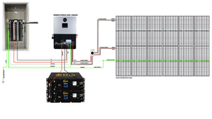
Here is what I put together from everything mentioned... Sorry for the blurry image, unable to upload the original as it's "too large"
NOTE: Only change I made was for the L1 & L2 which is 8/3 wire not 10/3.
Anything metal has to have an EGC ran to it or be connected by metallic conduit for an effective ground path.
HighCountry
New Member
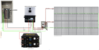
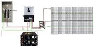
Made those updates and added metal box for PV isolator, obviously I don't have skills to make this out into detailed plans but the basics are there. Most everything runs through conduit underground. EG4 6000XP and batteries housed in a solar shed with panels about 100ft away. Conduit ran from solar shed to cabin where main breaker is located. Overall, I think this is the most basic setup for the EG4 6000XP can run, and frankly minimum of (3) EG4 LL-S batteries is ideal - like Johnny Cash song "one piece at a time..."
Attachments
Last edited:
HighCountry
New Member
Question: Does the ground from EGC at PV need to run directly to the main breaker panel?
Alternatively, could the EGC from panel go to the inverter then to the main breaker then to breaker by 8/3 used with L1/L2. Also, I understand that the EGC at PV needs to by bare copper 6 AWG min., but once at the disconnect and transition over to THWN-2 - from here on does it also have to remain 6AWG wire? In essense, bare copper 6 AWG to THWN-2 6 AWG (or 8 AWG?) to 8 AWG (8/3 UF).
NEC 250.66 and Table 250.66. The EGC is required to be a minimum size of 8 AWG copper if in a protected location (ie. conduit). Bare copper 6 AWG at panels to the disconnector box.
Zwy
Solar Wizard
Question: Does the ground from EGC at PV need to run directly to the main breaker panel?
No
Alternatively, could the EGC from panel go to the inverter then to the main breaker then to breaker by 8/3 used with L1/L2.
Yes, as long as you don't form a loop.
Also, I understand that the EGC at PV needs to by bare copper 6 AWG min., but once at the disconnect and transition over to THWN-2 - from here on does it also have to remain 6AWG wire? In essense, bare copper 6 AWG to THWN-2 6 AWG (or 8 AWG?) to 8 AWG (8/3 UF).
Size according to the current carrying conductors. My current carrying conductors are 10AWG but I could have used 12AWG.
Wrong section, you are looking at service entrance requirements.NEC 250.66 and Table 250.66. The EGC is required to be a minimum size of 8 AWG copper if in a protected location (ie. conduit). Bare copper 6 AWG at panels to the disconnector box.
2020 NEC: 690.45 Size of Equipment Grounding Conductors.
Equipment grounding conductors for PV system circuits shall be sized in accordance with 250.122. Where no overcurrent protective device is used in the circuit, an assumed overcurrent device rated in accordance with 690.9(B) shall be used when applying Table 250.122.
Increases in equipment grounding conductor size to address voltage drop considerations shall not be required.
Table 250.122 can be found on this page. https://codes.iccsafe.org/s/ISEP201...-nec-solar-provisions/ISEP2018-NEC-Sec250.122
HighCountry
New Member
HighCountry
New Member
Decided to get 3 EG4 LL-S batteries instead of two! And getting the server rack mostly because I want batteries in secure rack...
EG4_Jared
Online Support for EG4 Electronics
It is not recommended to ground the AC and DC grounds at the PEBus of the inverter.The ultimate plan. Thoughts...
Quattrohead
Solar Wizard
Where then ?It is not recommended to ground the AC and DC grounds at the PEBus of the inverter.
Zwy
Solar Wizard
I have to ask why.It is not recommended to ground the AC and DC grounds at the PEBus of the inverter.
If you have tested and came to this conclusion then share the info.
HighCountry
New Member
A basic wire diagram would be great!It is not recommended to ground the AC and DC grounds at the PE Bus [sic] of the inverter.
Last edited:
Similar threads
- Replies
- 11
- Views
- 677
- Replies
- 18
- Views
- 1K
- Replies
- 18
- Views
- 2K
- Replies
- 4
- Views
- 777


