Hello all.
I live very remotely with no access to grid power. I use a diesel generator without any real battery storage systems. I am in the process of adding a 48v battery system to power my house in the evenings so I can turn the generator off. Eventually, I will add solar to the system to charge the batteries, but I'm not there yet. I'm still new at this.
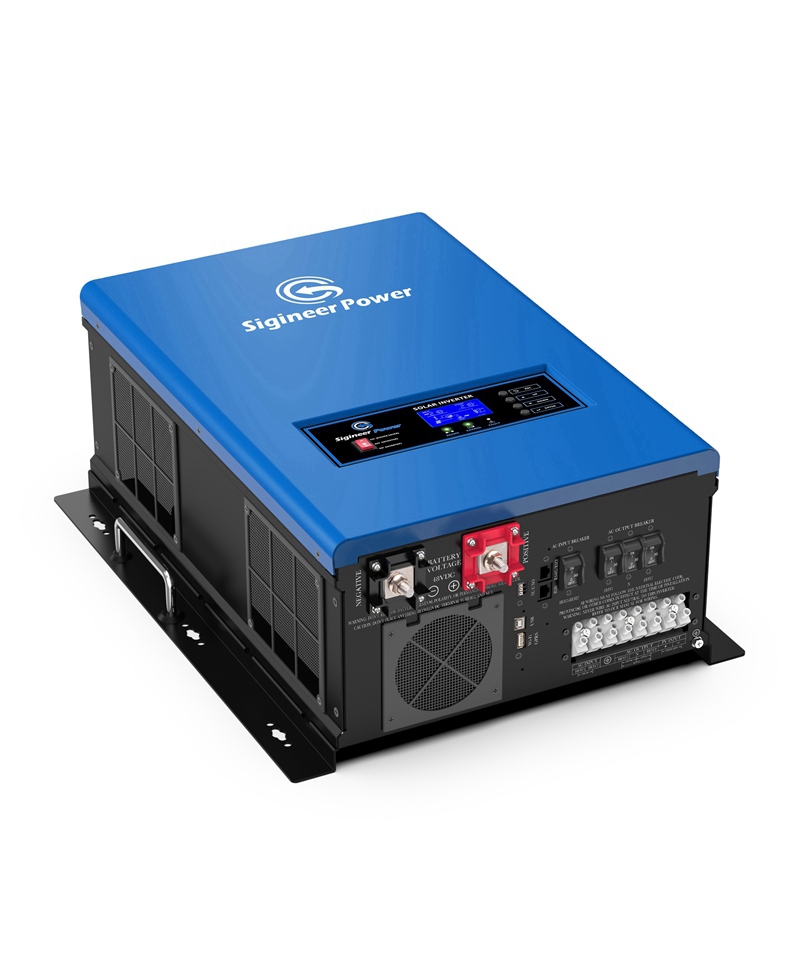
I recently purchased and hooked up a Sigineer M6048D 6KW inverter/charger. My generator puts out 240v through 3 conductors. 120v on each of two hot wires, plus a neutral (and a ground). That runs through a fuse box and then to a junction box that splits the power to run to a further three separate fuse boxes - one each for the barn, workshop, and house. All junctions are 240v so each fuse box receives the same power the generator puts out. Since I was only interested in running the house when the generator was off, I removed the house connection from the junction box. I then added a line from the junction box to the inverter input that requires the two hot wires and the ground (no neutral). Finally, the output of the inverter is wired back to the input of the house fuse box with both hots, a neutral, and a ground.
I have the inverter set up to only use battery power when it recognizes there is no power coming from the generator (or "utility" as the inverter calls it). If the generator is on, it presumably just passes the power straight from the generator to the house. It also charges the batteries when they need it through an Overkill Solar BMS.
In the old system, if I had a 120v heater pulling 10 amps in the house, I could measure the 10 amps with a clamp meter on the appropriate hot wire (leg 1) coming out of the generator. If I switched plugs so that the heater was drawing from the other hot wire (leg 2), I could see the 10 amps coming out of the other hot wire. After hooking up the inverter, no matter which plug I use, the generator puts out 5 amps on each hot wire. Well, obviously the inverter is doing some magic to spread the load evenly to each leg of the generator. Neat.
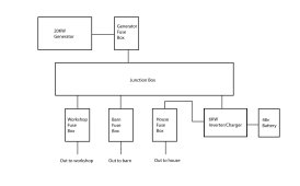
Here is the mystery: when I plug the same heater into an outlet in the workshop, the appropriate hot wire in the workshop fuse box shows a 10 amp draw, but THE GENERATOR STILL PUTS OUT 5 AMPS PER LEG. I have confirmed it multiple times with the clamp meter. I don't understand how the inverter even knows there is a draw coming from the workshop, or the barn. But all loads regardless if they are from the house, workshop, or barn all get equalized and pull the same amount from each leg of the generator. How does the fact that the inverter is drawing 240v from the junction box suddenly affect the whole system? I attached a little diagram to help visualize things. Am I ignorant, or is this magic?
I live very remotely with no access to grid power. I use a diesel generator without any real battery storage systems. I am in the process of adding a 48v battery system to power my house in the evenings so I can turn the generator off. Eventually, I will add solar to the system to charge the batteries, but I'm not there yet. I'm still new at this.
I recently purchased and hooked up a Sigineer M6048D 6KW inverter/charger. My generator puts out 240v through 3 conductors. 120v on each of two hot wires, plus a neutral (and a ground). That runs through a fuse box and then to a junction box that splits the power to run to a further three separate fuse boxes - one each for the barn, workshop, and house. All junctions are 240v so each fuse box receives the same power the generator puts out. Since I was only interested in running the house when the generator was off, I removed the house connection from the junction box. I then added a line from the junction box to the inverter input that requires the two hot wires and the ground (no neutral). Finally, the output of the inverter is wired back to the input of the house fuse box with both hots, a neutral, and a ground.
I have the inverter set up to only use battery power when it recognizes there is no power coming from the generator (or "utility" as the inverter calls it). If the generator is on, it presumably just passes the power straight from the generator to the house. It also charges the batteries when they need it through an Overkill Solar BMS.
In the old system, if I had a 120v heater pulling 10 amps in the house, I could measure the 10 amps with a clamp meter on the appropriate hot wire (leg 1) coming out of the generator. If I switched plugs so that the heater was drawing from the other hot wire (leg 2), I could see the 10 amps coming out of the other hot wire. After hooking up the inverter, no matter which plug I use, the generator puts out 5 amps on each hot wire. Well, obviously the inverter is doing some magic to spread the load evenly to each leg of the generator. Neat.
Here is the mystery: when I plug the same heater into an outlet in the workshop, the appropriate hot wire in the workshop fuse box shows a 10 amp draw, but THE GENERATOR STILL PUTS OUT 5 AMPS PER LEG. I have confirmed it multiple times with the clamp meter. I don't understand how the inverter even knows there is a draw coming from the workshop, or the barn. But all loads regardless if they are from the house, workshop, or barn all get equalized and pull the same amount from each leg of the generator. How does the fact that the inverter is drawing 240v from the junction box suddenly affect the whole system? I attached a little diagram to help visualize things. Am I ignorant, or is this magic?
")