Hedges
I See Electromagnetic Fields!
- Joined
- Mar 28, 2020
- Messages
- 21,079
Thanks for the good reference materials.
Some members at the backshed forum shared their design of inductor core saturation tester, but I did not have the time to build it and try.
Thanks for the mention of Backshed. It didn't turn up, just EEVblog, when I was searching from work.
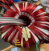
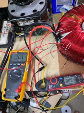
Variac is good to drive transformer winding. Current shoots up fast, so series resistor makes it more controllable. Can also provide current sense, if you don't have a current probe. Current transformer can also be used, but has about 100A range for 333 mV output, so not much signal at 1A or so.
Variac output is ground referenced and scope BNC terminals are grounded. An isolation transformer on output of Variac lets you establish a new ground, and can step up or down the voltage as needed. I use a step-down for chokes that saturate at a couple volts, and more of the Variac range can be used.
If using ground-referenced voltage probes for both winding voltage and sense resistor, of course same node for both grounds. Can also use identical second winding of transformer under test for voltage sense.
My earlier models just used voltage or inductance ratio to determine turns ratio. Inductance measured with network analyzer, impedance analyzer, or voltage/current sensed by scope at line voltage. Inductance with second winding open/short gives coupling coefficient.
The Variac, saturation, BH curve approach allows extraction of parameters for Chan model (easier to do graphically than number crunching a million data points, at least when I've tried to program it.) Chan does not include leakage inductance or resistance, so I add those as separate elements determined by my earlier method.
I've also measured inrush applying DC voltage, repeat same polarity and alternate. First time of a given polarity it holds off current for time period longer than one AC phase before shooting up. Second time, re-enters saturation in a couple milliseconds. Reverse and it holds off longer for one time. The current transformer (which has a core) couldn't capture rise time and peak, but Fluke probe which is flexible Rogowski coil (no core) has 20 kHz bandwidth and could.
I've used the Chan model primarily for chokes, got better simulation of their performance in a circuit. Core materials differ, and vendors usually don't provide all the parameters.