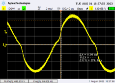
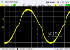
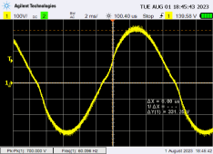
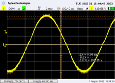
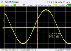
With the added capacitors, I used different resistive loads and here are the waveforms of the 220vac output.


You are using an out of date browser. It may not display this or other websites correctly.
You should upgrade or use an alternative browser.
You should upgrade or use an alternative browser.
Another Inverter build
- Thread starter tinyt
- Start date


Hedges
I See Electromagnetic Fields!
- Joined
- Mar 28, 2020
- Messages
- 21,481
Update:
Started load testing using a 7.5KVA resistive load, connected the 'scope at the 220vac output and observed that it is noisy. This is is with the existing 2.2uF capacitor at each output phase of the split phase toroid transformer.
Capacitor across output, so only "L" is parasitic of the low-frequency transformer (and maybe boost inductor)?
Explicit "L" may help. Or a leakier power transform instead of that nice toroid?
We're wrapping up a project using TDK/Lambda PFC module. No eval boards were available, and their test circuit used custom-wound inductors on commercial cores. We selected off the shelf common-mode chokes for input and output filter. The differential mode inductance is whatever leakage inductance it has.
But we had about 125 kHz switcher, so smaller filter works. I think your switching is about 1/10th of that.
The module we bought is 1.5kW, and our application is only half that, so smaller components than you would need.
(and ours is 360VDC, so low current.)
Something similar to these. It did do a decent job of cleaning up the switching current.


It also suppressed 120 Hz component (which we care about) somewhat, but being single stage boost, still has a discharge across the low voltage time of each 60 Hz cycle. Would need a buck stage as well to suppress that, or 3-phase PFC implementation.
We measured efficiency and power factor around 95% and 0.95, in line with vendor data sheets.
Thanks, if it affects the loads I will add similar power line filter and/or do some tuning of the toroid/inductor/capacitor combination. If I remember, warspeed suggested to tune it to 1.5 times the line frequency.Capacitor across output, so only "L" is parasitic of the low-frequency transformer (and maybe boost inductor)?
Explicit "L" may help. Or a leakier power transform instead of that nice toroid?
We're wrapping up a project using TDK/Lambda PFC module. No eval boards were available, and their test circuit used custom-wound inductors on commercial cores. We selected off the shelf common-mode chokes for input and output filter. The differential mode inductance is whatever leakage inductance it has.
But we had about 125 kHz switcher, so smaller filter works. I think your switching is about 1/10th of that.
The module we bought is 1.5kW, and our application is only half that, so smaller components than you would need.
(and ours is 360VDC, so low current.)
Something similar to these. It did do a decent job of cleaning up the switching current.
View attachment 160695
View attachment 160696
It also suppressed 120 Hz component (which we care about) somewhat, but being single stage boost, still has a discharge across the low voltage time of each 60 Hz cycle. Would need a buck stage as well to suppress that, or 3-phase PFC implementation.
We measured efficiency and power factor around 95% and 0.95, in line with vendor data sheets.
Warpspeed
Solar Wizard
A power line filter is always a good idea, but most of them only begin to have any really significant attenuation at well above 20 Khz, so select your filter carefully.
Failing that, it may still need more inductance in your large primary choke, to further reduce the high frequency ripple current in the primary.
Idling power is spectacularly good !
The overall efficiency will probably peak out at around a few hundred watts, and your overall efficiency figures are pretty typical.
It would be extremely difficult to improve on what you now have, so well done, a great achievement.
Found this cabinet, finish is powder coated. I think I am going to put everything inside this cabinet: Inverter, PV combiner/monitor(to be designed), SCC, controller/monitor (tbd), Wifi module, forced air cooling, etc. I intend to use home assistant.

So, I think this part of the project is finished and I will be moving on to the next phase.
That's all folks.
So, I think this part of the project is finished and I will be moving on to the next phase.
That's all folks.
Hedges
I See Electromagnetic Fields!
- Joined
- Mar 28, 2020
- Messages
- 21,481
Ventilation?
Something like an inverter will expel hot air, and recirculate back to it's input.
Separately ventilating enclosure should help, but interior will run hotter than exterior.
I would prefer to exhaust hot air through duct to outside the enclosure.
Something like an inverter will expel hot air, and recirculate back to it's input.
Separately ventilating enclosure should help, but interior will run hotter than exterior.
I would prefer to exhaust hot air through duct to outside the enclosure.
Included in the edited post, will add air inlet and outlet ports. Thanks for the reminder.Ventilation?
Something like an inverter will expel hot air, and recirculate back to it's input.
Separately ventilating enclosure should help, but interior will run hotter than exterior.
I would prefer to exhaust hot air through duct to outside the enclosure.
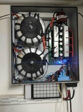
Hello everyone, congratulations for the great work you have done.I limited myself to taking a Chinese 24 MOS module at 48 volts, two 3000 VA toroids in series with 11 + 11 primary turns of 35 mm2 and 230 volt windings in parallel.It has been working for about 4 months and has delivered 1200 kW without ever a problem. With a two kW load it has an efficiency of 95% tested up to 5.5 kW.my main fear is the 80 volt hy4008 mosfets and the batteries go up to 56 volts...for this reason I got a similar inverter board but without mosfet to do some tests, if anyone can give me some advice on the choice it would do me a great favor.
I attach the photo of my work
best regards
Mauro
I attach the photo of my work
best regards
Mauro
Attachments
Hedges
I See Electromagnetic Fields!
- Joined
- Mar 28, 2020
- Messages
- 21,481
Only 11 turns for primary? (x2 with transformers in series).
What turns ratio or voltage ratio?
I would think 230V x 2^2 / 48V is in the range you want, but I would have thought existing windings would have much more than 149 turns.
Were those just inductors? Or transformers, and you only used one existing winding?
Does it drive PWM into primary?
Have scope images?
When you enclose it and use force air. Be sure to bring up load and extend time slowly so the you periodically quickly open and inspect temperatures. Dead air spaces can be surprisingly tricky to figure out and you may need to make direction changes and/or diverters.
Thanks for the replies
they were two 220 volt 48 volt transformers, I removed the 48 volt part and replaced it with 11 coils of approximately 13 volts as requested, I have no idea what ratio it has but given the performance I left it like that.
in the lower part there is a tangential fan and the upper part has an exhaust slot, even at 4 kW the radiators can be touched with your hands.
I have a movie of the sine wave with 1.6 kw of load.
Nice and neat arrangement.Hello everyone, congratulations for the great work you have done.I limited myself to taking a Chinese 24 MOS module at 48 volts, two 3000 VA toroids in series with 11 + 11 primary turns of 35 mm2 and 230 volt windings in parallel.It has been working for about 4 months and has delivered 1200 kW without ever a problem. With a two kW load it has an efficiency of 95% tested up to 5.5 kW.my main fear is the 80 volt hy4008 mosfets and the batteries go up to 56 volts...for this reason I got a similar inverter board but without mosfet to do some tests, if anyone can give me some advice on the choice it would do me a great favor.
I attach the photo of my work
best regards
Mauro
'Wiseguy' at 'thebackshed' forum created a list of mosfet devices.
Thanks, this is a very useful list.
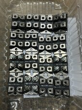
I have 20 ste110na20 isotop mosfets 200 volts 110 amperes 15 milliohm... not high specs but they are insulated and dissipate heat better, also I could make connections with copper bars reducing losses.
Do you think it's worth trying them or getting something else with less RDSON?
I have 20 ste110na20 isotop mosfets 200 volts 110 amperes 15 milliohm... not high specs but they are insulated and dissipate heat better, also I could make connections with copper bars reducing losses.
Do you think it's worth trying them or getting something else with less RDSON?
Attachments
Warpspeed
Solar Wizard
I think you might need at least two of those in each leg, or eight or twelve total for 90 amps dc, it should work.Do you think it's worth trying them or getting something else with less RDSON?
That 110 amp rating is for a junction temperature of only 25C, you need to de rate that hugely to work reliably at actual final running temperatures.
Bolted in devices are always a lot easier to replace than soldered in devices.
Also, any violent mishap tends to be completely contained within the device.
After many years of designing and building my own inverters, using the larger more expensive single devices always ends up producing a neater easier to work on final result. More recent devices have much better specs, but the cost of those can be horrific.
Similar threads
- Replies
- 12
- Views
- 309
- Replies
- 4
- Views
- 150
- Replies
- 14
- Views
- 303