


You are using an out of date browser. It may not display this or other websites correctly.
You should upgrade or use an alternative browser.
You should upgrade or use an alternative browser.
Another Inverter build
- Thread starter tinyt
- Start date

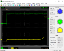
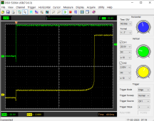
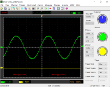
After some changes, I got the following timings at 47 volts and at 58 volts input. Green trace is at toggle switch on and yellow trace is the mosfet gate signal. At 47volts input, delay is 332 milliseconds and at 58 volts input, delay is 288 milliseconds. There is a 1.5 volts step prior to desired delay voltage, if this turns on the mosfets, I will have to do some more changes.
Major issue is at toggle switch power off, it takes more than 1.5 minutes for the timing capacitor to fully discharge, I will have to change the relay to DPDT and use the second pole COM-NC contacts to discharge the timing capacitor.
Major issue is at toggle switch power off, it takes more than 1.5 minutes for the timing capacitor to fully discharge, I will have to change the relay to DPDT and use the second pole COM-NC contacts to discharge the timing capacitor.
Attachments
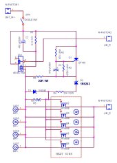
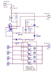
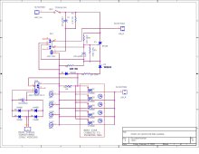
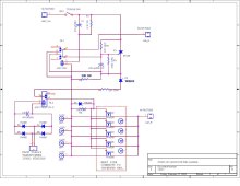
Schematic error: RL1 pin 4 should be connected to BAT-, introduced after gerber files were done during my troubleshooting. PCB is good for this connection. Attached is the corrected schematic. Also added note about inverter connection to heatsink.
Attachments
Warpspeed
Solar Wizard
Only potential problem I can see, is that this turns itself fully on after a set time delay.
If the inverter has failed due to some fault condition, there may be one hell of a bang when this circuit suddenly applies full power to it.
The soft start using mosfets instead of a big wire wound resistor, is a good idea.
But what I feel it needs, is not to apply full unrestricted dc power to the inverter until the inverter has successfully started up.
How about a small transformer/rectifier connected across the inverter output that supplies full isolated dc gate drive to all your 5608's but only once the inverter is actually running ?
The big electrolytics in the inverter will then provide the required start up delay.
A 15v dc wall pack plugged into the inverter output maybe ?
That will then do automatically what I do manually.
I push a button to power up the inverter through the start up resistor.
Only after I see that the 230v is fully up do I close the main dc breaker to the inverter.
If the inverter fails to start for any reason, the big bang at start up problem might be avoided.
Last edited:
Good idea, I'll see if I can incorporate it in revision 2. I can use the 12vac transformer I have removed from the inverter PCB or use the extra 10vac (for fans) winding of the toroid.Only potential problem I can see, is that this turns itself fully on after a set time delay.
If the inverter has failed due to some fault condition, there may be one hell of a bang when this circuit suddenly applies full power to it.
The soft start using mosfets instead of a big wire wound resistor, is a good idea.
But what I feel it needs, is not to apply full unrestricted dc power to the inverter until the inverter has successfully started up.
How about a small transformer/rectifier connected across the inverter output that supplies full isolated dc gate drive to all your 5608's but only once the inverter is actually running ?
The big electrolytics in the inverter will then provide the required start up delay.
A 15v dc wall pack plugged into the inverter output maybe ?
That will then do automatically what I do manually.
I push a button to to power up the inverter through the start up resistor.
Only after I see that the 230v is fully up do I close the main dc breaker to the inverter.
If the inverter fails to start for any reason, the big bang at start up problem might be avoided.
Hope this works, I have ordered the relays to find out.Good idea, I'll see if I can incorporate it in revision 2. I can use the 12vac transformer I have removed from the inverter PCB or use the extra 10vac (for fans) winding of the toroid.
Attachments
Update:
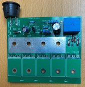
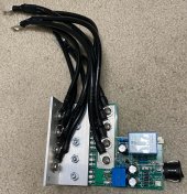
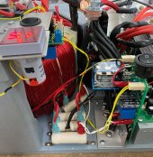
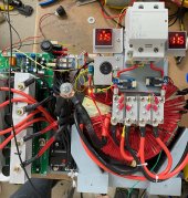
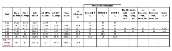
Finally got the rev 2 pre-charge pcb built. In case of inverter malfunction, I added a normally closed thermal switch in series with the switch and located it close to the pre-charge resistors. Also added on a separate pcb a relay to delay turn on of the contactor for the AC output. This prevents the inverter from soft starting with AC loads connected. The additional circuits and contactor increased the no-load power draw from 18.2 watts to 21 watts.
Finally got the rev 2 pre-charge pcb built. In case of inverter malfunction, I added a normally closed thermal switch in series with the switch and located it close to the pre-charge resistors. Also added on a separate pcb a relay to delay turn on of the contactor for the AC output. This prevents the inverter from soft starting with AC loads connected. The additional circuits and contactor increased the no-load power draw from 18.2 watts to 21 watts.
Attachments

Update (yes I have not forgotten):
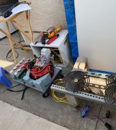
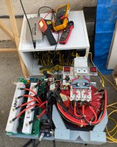
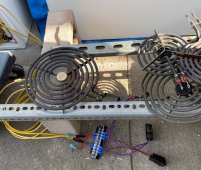
Finally did some load testing. Here is my setup, outside the house for safety. The power supply is diy 54 volts 94 amperes consisting of 18 ac-dc power bricks each rated at 5.2 amps, purchased years ago from a surplus store. The load will be some electric stove heating elements (220 volts).
Finally did some load testing. Here is my setup, outside the house for safety. The power supply is diy 54 volts 94 amperes consisting of 18 ac-dc power bricks each rated at 5.2 amps, purchased years ago from a surplus store. The load will be some electric stove heating elements (220 volts).
Attachments
And so, the troublshooting begins:
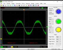
Looks like the 200A inductor from china is not good enough. There is too much pwm switching noise. Scope is attached to the 10vac winding of the toroid.
Looks like the 200A inductor from china is not good enough. There is too much pwm switching noise. Scope is attached to the 10vac winding of the toroid.
Attachments
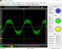
And because of the switching noise at high loads, the scr in the capacitor pre-charge pcb turns off removing the gate voltage to the mosfets. I will need to filter this before I continue load testing. One consolation is there no smoke or fire during the testing and I hope it stays that way.
Hedges
I See Electromagnetic Fields!
- Joined
- Mar 28, 2020
- Messages
- 21,079
What switching frequency? Can you increase it to reduce size of sawtooth? Or will that overheat parts besides reducing efficiency? (don't know how much of your losses are transistor transitions.)
Had you calculated that inductance should give lower ripple, and is this a saturation issue, making inductance lower?
Resistive load of course is the nicest. And heating elements are linear, unlike light bulbs, as nice as nice can be.
When you're feeling lucky you can try motor loads and non-PF corrected power supplies.
Had you calculated that inductance should give lower ripple, and is this a saturation issue, making inductance lower?
The load will be some electric stove heating elements (220 volts).
One consolation is there no smoke or fire during the testing and I hope it stays that way.
Resistive load of course is the nicest. And heating elements are linear, unlike light bulbs, as nice as nice can be.
When you're feeling lucky you can try motor loads and non-PF corrected power supplies.
I am using EGS002 module with EG8010 chip that has 23.4Khz frequency for the sinewave pwm.What switching frequency? Can you increase it to reduce size of sawtooth? Or will that overheat parts besides reducing efficiency? (don't know how much of your losses are transistor transitions.)
Had you calculated that inductance should give lower ripple, and is this a saturation issue, making inductance lower?
Resistive load of course is the nicest. And heating elements are linear, unlike light bulbs, as nice as nice can be.
When you're feeling lucky you can try motor loads and non-PF corrected power supplies.
I have not calculated/measured the inductance of the choke, and I have not made a saturation tester yet.
Resistive load for now, then other loads including the dreaded half-wave hair dryer in low heat setting.
Still a lot of work to do.
Hedges
I See Electromagnetic Fields!
- Joined
- Mar 28, 2020
- Messages
- 21,079
Ramp of sawtooth vs. current should give inductance. Compare inductance at peak of sine wave with lower points to see if it is getting into saturation.
I had fun getting BH curve using variac and scope, then trying to make LTSpice model. Successful with some components but not others. I don't know how important hysteresis is for your application (except for its loss) but saturation of course is.
I also tested saturation and hysteresis of transformer using CV/CC supply and scope. First time after reversing polarity it held off the current for a number of milliseconds longer than a phase, second time just a couple milliseconds before shooting up into saturation. That's what transformer inrush comes from.
Warpspeed
Solar Wizard
It appears to me, that the inductance of the choke is gradually reducing with increasing load current.
That is to be expected, and a gradual decrease, is a lot better (and safer) than hitting a sudden brick wall at saturation.
Its also highly likely that the voltage you are seeing across the 10 volt winding is not representative of the voltage across the 230 volt output winding.
The reason for that, is the ten volt winding will have a lot less self capacitance, and a much better high frequency response.
The 230v winding will have a LOT more of both inductance and capacitance, and hence a much lower self resonant frequency, which will be well below 23Khz. That in itself will greatly increase the attenuation of the 23Khz PWM residual seen on the 50Hz output.
Suggest you try connecting a 230v to 12v (?) transformer across the 230 v inverter output and look at the secondary voltage of that.
Pretty sure that will look a lot cleaner.
Overall an EXCELLENT result, and something to be really proud of !
Last edited:
RCinFLA
Solar Wizard
- Joined
- Jun 21, 2020
- Messages
- 3,566
Filter inductor core is saturating as 60 Hz load current increases.
The 60 Hz low freq current is like large DC bias flux on filter inductor core saturating it. When it approaches saturation the effective inductance plummets reducing the high frequency PWM filtering. This is why the HF ripple increases at peaks of 60 Hz waveform where the 60Hz current is greatest.
Core size and number of turns flux density must stay out of saturation for the peak 60 Hz bias current created core flux.
Suggest using Mega Flux Cores.
Design info at:
1) Pick a core.
2) Calculate number of turns required for PWM frequency filter inductance.
3) Check flux density (amp-turns) from charts for selected core saturation at peak 60 Hz current (plus some margin).
4) If too close to saturation, select a larger core and repeat starting with step 2.
5) Determine wire gauge to handle peak 60 Hz current
6) Check if required wire gauge and number of turns fits on core. (You can use multiple parallel smaller gauge wires to accomplish 60 Hz current handling).
7) If not, select a larger core and repeat starting with step 2.
Core material selected should not be too lossy at PWM frequencies.
Improper PWM L-C filter design is one of the primary causes of excessive inverter no-load idle current. Low reactive loading due to PWM filtering increases inverter idle current. Higher impedance L-C filter (more inductance, less capacitance) reduces idle current but the inductor core must be larger (and more expensive) due to the greater amp-turns of filter inductor to prevent core saturation under peak low frequency AC load current.
For LF inverter designs, the PWM filter is usually done with inductor in series with high current primary and capacitor placed on secondary side of LF transformer. On first approximation, the design of PWM filter can be modelled on primary side, then capacitor impedance transformed to secondary side of LF transformer. The LF transformer is not perfect for HF PWM frequencies but is usually acceptable to approximate as an idea impedance transform that reduces the shunt capacitor value on secondary side of LF transformer by the turns ratio of LF transformer.
The 60 Hz low freq current is like large DC bias flux on filter inductor core saturating it. When it approaches saturation the effective inductance plummets reducing the high frequency PWM filtering. This is why the HF ripple increases at peaks of 60 Hz waveform where the 60Hz current is greatest.
Core size and number of turns flux density must stay out of saturation for the peak 60 Hz bias current created core flux.
Suggest using Mega Flux Cores.
Design info at:
Data on MPP, Sendust, and High Flux Cores. : Coil Winding Specialist, Inc.
Coil Winding Specialist, Inc. : Data on MPP, Sendust, and High Flux Cores. - Products Specification & Properties About Us LOG IN HOME Other Services coil, ecommerce, open source, shop, online shopping, store
www.cwsbytemark.com
1) Pick a core.
2) Calculate number of turns required for PWM frequency filter inductance.
3) Check flux density (amp-turns) from charts for selected core saturation at peak 60 Hz current (plus some margin).
4) If too close to saturation, select a larger core and repeat starting with step 2.
5) Determine wire gauge to handle peak 60 Hz current
6) Check if required wire gauge and number of turns fits on core. (You can use multiple parallel smaller gauge wires to accomplish 60 Hz current handling).
7) If not, select a larger core and repeat starting with step 2.
Core material selected should not be too lossy at PWM frequencies.
Improper PWM L-C filter design is one of the primary causes of excessive inverter no-load idle current. Low reactive loading due to PWM filtering increases inverter idle current. Higher impedance L-C filter (more inductance, less capacitance) reduces idle current but the inductor core must be larger (and more expensive) due to the greater amp-turns of filter inductor to prevent core saturation under peak low frequency AC load current.
For LF inverter designs, the PWM filter is usually done with inductor in series with high current primary and capacitor placed on secondary side of LF transformer. On first approximation, the design of PWM filter can be modelled on primary side, then capacitor impedance transformed to secondary side of LF transformer. The LF transformer is not perfect for HF PWM frequencies but is usually acceptable to approximate as an idea impedance transform that reduces the shunt capacitor value on secondary side of LF transformer by the turns ratio of LF transformer.
Last edited:
Re-reading this post in TheBackShed maybe I can also learn more and remember.
In addition to no-load idle current, another issue I have seen is that many if not most systems have chokes saturation close to the nominal rated current which is not nearly adequate for surge loads. Surge DC current can often be 5x+ the nominal rated current. The result is saturated choke under surge load that leads to degradation and potentially destruction.Improper PWM L-C filter design is one of the primary causes of excessive inverter no-load idle current. Low reactive loading due to PWM filtering increases inverter idle current. Higher impedance L-C filter (more inductance, less capacitance) reduces idle current but the inductor core must be larger (and more expensive) due to the greater amp-turns of filter inductor to prevent core saturation under peak low frequency AC load current.
Similar threads
- Replies
- 16
- Views
- 883
- Replies
- 12
- Views
- 622