I would appreciate any feedback, especially if you see something wrong or something that could be improved. I didn't go crazy with fuses since I thought the battery BMS would basically shut down if something went wrong, but I will gladly add fuses or anything else, if recommended.
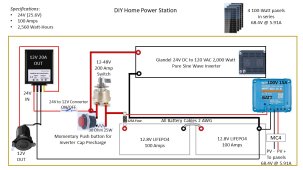
With the exception of the 2 AWG battery cables (on order), I'm ready to start building this DIY power station in a RIGID 2.0 25" box on wheels.
Please let me know if you see anything wrong or anything you would do differently to make it safer.
Thanks in advance for your help.
Bob
Some questions I have are:
1. I believe the two AWG 2 cables from the batteries to the Inverter MUST be the same length, but can I put a shorter cable BETWEEN the two batteries in series since they will be literally 3 inches away from each other?
2. I didn't plan on a switch to turn off the panel voltages going to the solar charge controller since I plan on rolling out the cart and solar panel stands, and then connecting the MC4 connectors. I can always turn the panel stand away from the sun, connect the MC4s, and then position the panels if the 68V would cause a problem pushing the MC4 connectors together.
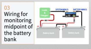
3. I purchased two LIFEPO4 battery meters that can be programmed to monitor each 12V battery or monitor both batteries in series. Would you suggest I monitor each separately? Or monitor them in series? The meters display the voltage and also display the battery capacity (e.g., 80%, 90%) based on the battery voltage (e.g., 13.2V=70%, 13.3V=90%, 13.6V=100%).
With the exception of the 2 AWG battery cables (on order), I'm ready to start building this DIY power station in a RIGID 2.0 25" box on wheels.
Please let me know if you see anything wrong or anything you would do differently to make it safer.
Thanks in advance for your help.
Bob
Some questions I have are:
1. I believe the two AWG 2 cables from the batteries to the Inverter MUST be the same length, but can I put a shorter cable BETWEEN the two batteries in series since they will be literally 3 inches away from each other?
2. I didn't plan on a switch to turn off the panel voltages going to the solar charge controller since I plan on rolling out the cart and solar panel stands, and then connecting the MC4 connectors. I can always turn the panel stand away from the sun, connect the MC4s, and then position the panels if the 68V would cause a problem pushing the MC4 connectors together.
3. I purchased two LIFEPO4 battery meters that can be programmed to monitor each 12V battery or monitor both batteries in series. Would you suggest I monitor each separately? Or monitor them in series? The meters display the voltage and also display the battery capacity (e.g., 80%, 90%) based on the battery voltage (e.g., 13.2V=70%, 13.3V=90%, 13.6V=100%).


") . Since I have a Victron SCC, I'll get that one and wire it up like the attached picture shows. I guess I should have known that the $9 battery capacity meter wasn't going to work! I was hoping to build my entire project for $1,000 or less, but I can see that's not going to happen. I probably should have waited for the VTOMAN Pro 3000...but I guess I'll learn a lot more doing it DIY and it will be much easier to repair/replace individual components rather than an entire power station. These days, it's difficult and expensive to even ship the power stations purchased online. Thanks again for that info on monitoring 2 batteries in series. I'm learning more and more on this website and sincerely appreciate everyone's help.
. Since I have a Victron SCC, I'll get that one and wire it up like the attached picture shows. I guess I should have known that the $9 battery capacity meter wasn't going to work! I was hoping to build my entire project for $1,000 or less, but I can see that's not going to happen. I probably should have waited for the VTOMAN Pro 3000...but I guess I'll learn a lot more doing it DIY and it will be much easier to repair/replace individual components rather than an entire power station. These days, it's difficult and expensive to even ship the power stations purchased online. Thanks again for that info on monitoring 2 batteries in series. I'm learning more and more on this website and sincerely appreciate everyone's help.