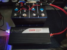
Hi community!
I've ordered 4 pcs LF280 Grade A Cells from Docan Tech (based on forum info).
It arrived with exact the same voltage of 3.290V and IR = 0.20mOm.
I'm using 200A JK BMS B2A8S20P (2A balance charge) and a Heltec 10A Active balancer + 38A CC/CV AC/DC power supply for charging.
I've charged the battery to 13.8V and the max voltage difference was 30mV so I decided that there is no need for Top Balancing the cells.
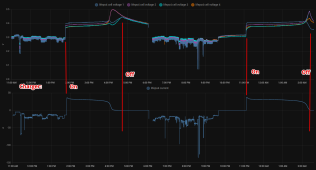
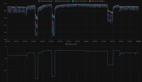
We have few scheduled electricity shutdowns per day and I'm using about 20-30% of battery energy per cycle. All this time the cells was balanced.
But after 2 weeks I've managed to connect the BMS to ESPHome and received more detailed data on the cells.
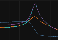
I see that Cell3 and Cell4 performs the same
the Cell 1 is every time goes up when charging and down when discharging.
Cell 2 is in between.
Should I worry about this?
-------------
And the second part is about the charger.
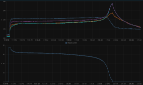
I'm using Eltek SMPS1000 10-30V DC power supply. It has Current limit circuit but I'm using it on max current it can provide (up to 39A)
I settled on it the 13.8V without the battery connected. On the charts you can see how the charging goes on. Is this ok for the battery or should I use more smart charger to be able to set higher voltage to achieve CC stage and then drop it to 13.8V?
Is it safe to leave the charger always connected with 13.8V when the current drops to 0A?
Thanks in advance for your suggestions.
Last edited:


