Fran365
New Member
- Joined
- May 2, 2021
- Messages
- 59
I am.Is an inverter precharge appropriate in this situation?


I am.Is an inverter precharge appropriate in this situation?
I have a 150 Amp Class-T fuse between my batteries and the controller/inverter, 3000 watts. My system is designed to pull 2k max.Gents, I have determined a 150 Amp main fuse between battery and inverter, sound right for a 2000watt, 24 volt inverter. What inverter position would maximize heat loss: terminals up or down. While here, I plan to attach a extension cord remnant to the inverter 110v out receptacle, and lead it to a work box, at a convenient spot, with a gfi, any issues with these ideas. Note, I presently have 2 200 watt 24 volt solar panels to get this up and running.
That is a shunt.
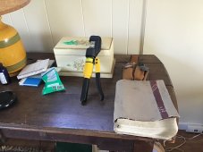
That is a pretty cool compact setup but the bungee cord will give up its tension after a bit and I think your Epever is upside down. Dust will fall into the unit.
I do not know what the black/blue/yellow box is.
My signature contains a link to battery info. It is a great read before assembling high amp stuff.
That is a great idea, charge from the grid when needed.It's a transfer switch:
Amazon.com: MOES Dual Power Controller 50A 5500 Watt Automatic Transfer Switch for Off Grid Solar Wind System ATS DC 12V 24V 48V AC 110V 220V: Garden & Outdoor
Amazon.com: MOES Dual Power Controller 50A 5500 Watt Automatic Transfer Switch for Off Grid Solar Wind System ATS DC 12V 24V 48V AC 110V 220V: Garden & Outdoorwww.amazon.com
Will has a video testing that model. Seems like it's not bad for the money.
Yes, WYT, the bungees are already weakening. Thanks for all.That is a pretty cool compact setup but the bungee cord will give up its tension after a bit and I think your Epever is upside down. Dust will fall into the unit.
I do not know what the black/blue/yellow box is.
My signature contains a link to battery info. It is a great read before assembling high amp stuff.
I don’t completely understand this thing but the positives seem good. Let’s say we have a situation where sun is poor and we have rolling blackouts, or power 4 hours a day: you could accumulate power to the batteries when possible, automatically.That is a great idea, charge from the grid when needed.
The product does not appear to be UL listed. I have to wonder what an insurance company, utility company or inspector would say if they saw it wired to the grid.
That is not a charge transfer switch.That is a great idea, charge from the grid when needed.
Yes- a possible exception is that if battery cable goes down on busbar first and the busbar lugs are nice quality, clean and flat you ‘could’ technically stack the inverter feed cable lug on top of the battery lug before installing washers and nut if terminal ends are large and robust. That is direct contact without the busbar in between. Of course there needs to be a breaker or fuse somewheres appropriate.Yes only one, flat against it. If necessary double low amperage terminals. All wire sizes should be determined by the amps that they will carry.
Is there an updated layout with new/different components?Yes, WYT, the bungees are already weakening. Thanks for all.
I don’t completely understand this thing but the positives seem good. Let’s say we have a situation where sun is poor and we have rolling blackouts, or power 4 hours a day: you could accumulate power to the batteries when possible, automatically.
That is not a charge transfer switch.
It elects the grid input when batteries discharge to a predetermined point, and back to batteries/solar when they are above a certain voltage.
Yes- a possible exception is that if battery cable goes down on busbar first and the busbar lugs are nice quality, clean and flat you ‘could’ technically stack the inverter feed cable lug on top of the battery lug before installing washers and nut if terminal ends are large and robust. That is direct contact without the busbar in between. Of course there needs to be a breaker or fuse somewheres appropriate.
No advantage other than if you need the other large studs for other things. In OP’s case probably not.
Nothing else should be stacked. The stud and washers and nut are not where you want to depend on to have current flow; they do in fact conduct electricity but their job is to provide very tight connection with the busbar, not conduct the load current. The threaded stud is there to provide clamping pressure
.
Hi WYT, no: right now I’m hacking through my ignorance on details. I have a new crimper to learn about. I’m trying to buy stuff for the long haul. I soon will be assembling my board.Is there an updated layout with new/different components?
ThanksThat is not a charge transfer switch.
It elects the grid input when batteries discharge to a predetermined point, and back to batteries/solar when they are above a certain voltage.
There is more to learn than can be imagined.Hi WYT, no: right now I’m hacking through my ignorance on details. I have a new crimper to learn about. I’m trying to buy stuff for the long haul. I soon will be assembling my board.
Thanks again WYT, the crimper comes with a little book and it gives awg, csa(mm2) and the manufacturers die number. 4 awg is 21.1 csa( mm2) and manufacturers number 25. I’m in central Indiana, nice to meet you.There is more to learn than can be imagined.
The crimper is a great idea. The dyes are probably metric, the crimps are usually SAE, assuming you are in the US.
EDIT: The link in my signature on "battery melt down" will provide you with great info on how to properly use the crimper and assemble some parts. There is a great deal of other info on that site.
I took your advice, the subject is posted and anyone interested knows what to do. Ia chit chat the proper place?The balance of your post is more appropriate in "OFF TOPIC". Here we talk about solar systems. Perhaps an edit is in order.
That is a great idea, charge from the grid when needed.
The product does not appear to be UL listed. I have to wonder what an insurance company, utility company or inspector would say if they saw it wired to the grid.
Your links are rich and useful, thanks again. Is it wise to use electrician gloves when working with 24 v?There is more to learn than can be imagined.
The crimper is a great idea. The dyes are probably metric, the crimps are usually SAE, assuming you are in the US.
EDIT: The link in my signature on "battery melt down" will provide you with great info on how to properly use the crimper and assemble some parts. There is a great deal of other info on that site.
Hi WYT, I was all set this A M to crimp terminals and mount my system. The crimper is simple, but 3 try’s, with proper terminals and wire size,left a crimp that would not hold the wire. The instructions say you can loose pressure and to pump it to regain pressure but that didn’t work. It’s going back and I have a different type coming.There is more to learn than can be imagined.
The crimper is a great idea. The dyes are probably metric, the crimps are usually SAE, assuming you are in the US.
EDIT: The link in my signature on "battery melt down" will provide you with great info on how to properly use the crimper and assemble some parts. There is a great deal of other info on that site.
Hi WYT, I was all set this A M to crimp terminals and mount my system. The crimper is simple, but 3 try’s, with proper terminals and wire size,left a crimp that would not hold the wire. The instructions say you can loose pressure and to pump it to regain pressure but that didn’t work. It’s going back and I have a different type coming.

 diysolarforum.com
I have some lever crimpers that work by blood pressure. Rotate die for 6-0ga and they work good. I’ve actually used the for 2/0 by going progressively and not single-shot. I think they were $40-$45USIt’s going back and I have a different type coming.