diy solar

diy solar

ATS causing power surge inverter damage.

I don't know what kind of inverter he has but mine (600 W PSW Xantrex) had a GFI circuit that had similar behavior. Figures that if Line and Neutral don't switch (as in at the exact same time) within the time allocated then the GFI tripped. The outlet just like one in a bathroom and needed the button pushed in to reset. I just got into that inverter and took out the GFI outlet (put a stand alone one in "downstream"). But I hear you on the LED lights, as that wouldn't be inductive.

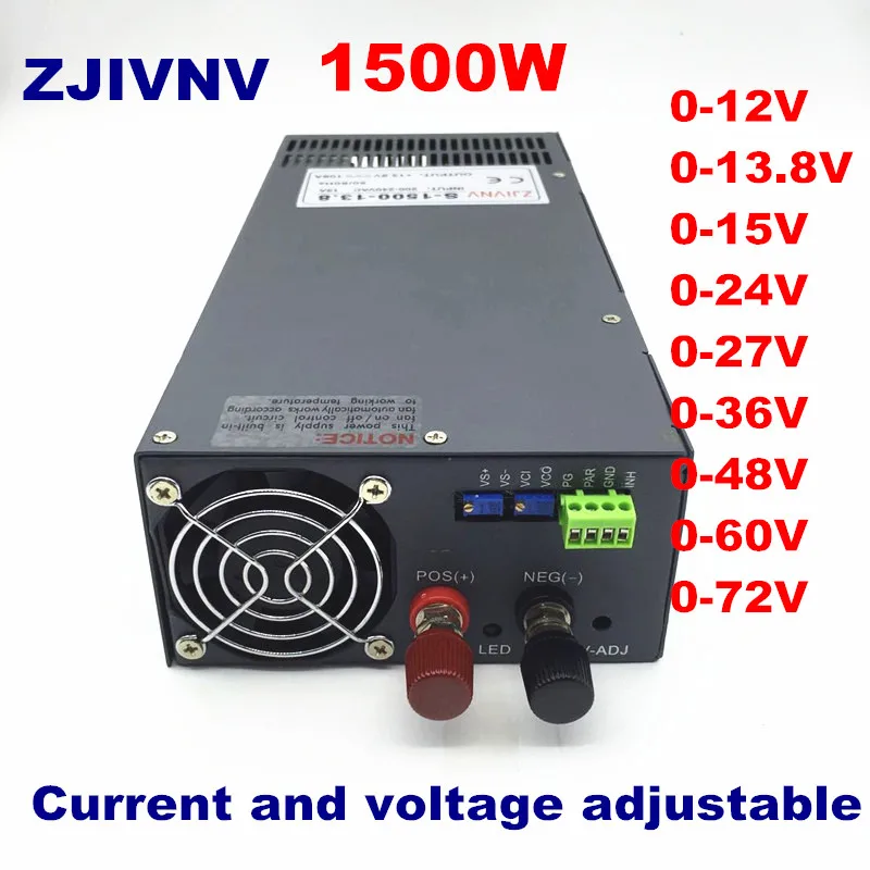
I have given "things" a little more thought (note that my youngest flew the coop last summer and I have a PT job of only 5 hrs/wk so have lots of time to devote to lots of things) and I looked around at a whole bunch of PSW inverter circuits this morning. Intriguing as to how many different types of circuits are out there. One 1000 W inverter design had 10 pairs of MOSFETs and one each of the pairs fed a 60 V and the other a -60 V all in tandem. Another design had some circuitry upstream from what appeared to be the power stages which encompassed only 4 solid state devices (didn't look too closely as to what type of "transistor"). Point is that same amount of power stage (as in what goes to our MOES) done with 4 devices vs 20. Thus I would hypothesize that the first inverter could be more robust.

Another approach may be to utilize a NTC in series on both Line/Neutral. NTC...Negative temperature coefficient thermistor. I'd not heard of one of these until today. It has high(ish) resistance (seems they are available in 1-20 ohms and max steady state currents around 10 Amps) until current applied and then goes down to a fraction of an ohm. Maybe couple that with a varistor across to L and N. A varistor has very high resistance at nominal operating voltage but then in an overvoltage state the resistance goes down...which would shunt any high voltage spikes.

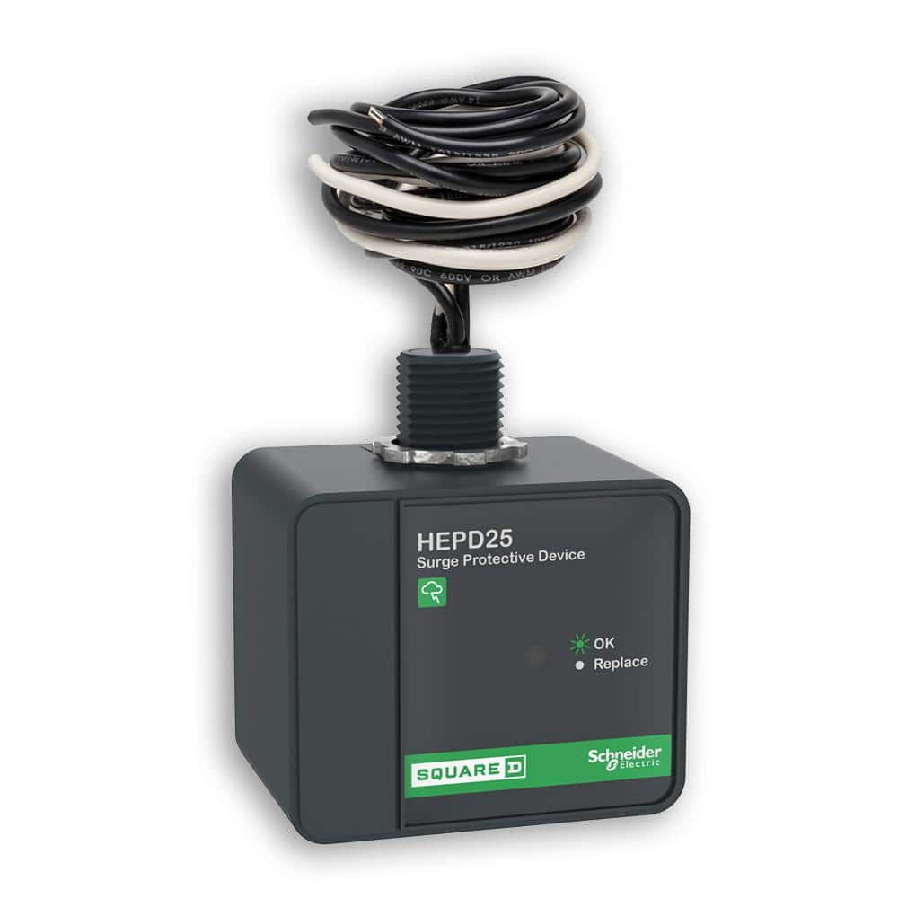
I suspect this wheel has already been invented and for instance HD in my area has this in stock...whole house surge protector. I suspect its guts have at least a varistor inside and I think could be adapted to our issue. You might google "parallel surge suppressors". I'm going to spend some time trying to figure out what's inside one of these.

 
Still looking for what is inside the Square D device above but here's a tear down of a European surge protector. Educational at least!


Here's a ~$10 Belkin with a tear down and schematic. Looking at the schematic (which doesn't include the LED circuitry) it looks to me as if the protection could/should work in either direction...so why not plug this into inverter and then the MOES into this? Wouldn't even need to hack this at all. That said, it's a voltage clamp/dissipating device (using varistors) and not a current surge device as far as I can tell. I would appreciate it if someone could chime in with the inductive load waveform characteristics. Over voltage, overvoltage and overcurrent, or just overcurrent? BTW, I happen to know the thermal fuses mentioned are just that...they fuse and don't work again even if/when temp goes down. Have replaced on air fryer and more recently coffee maker.
 
wow could it be that simple,18$ on amazon,but does that surge go both ways and when you get that surge are you buying another surge protector ,i like where this is going
 
As I previously wrote (and to date nobody has commented nor refuted) I think the inverter damage most likely occurring when switching from grid to inverter. Yes, could be a very simple solution unless it's an overcurrent event. This device is set up for over-voltage (clamping, ie send the energy to ground or into varistors, or both) and not overcurrent. But as I mentioned, looking at the teardown schematic it seems that the device should protect in either direction...so only one needed...and somewhere in the chain between the inverter and the Moes. I'd mentioned that I had removed the GFI outlet from my inverter (put a stand alone gfi later, but before the loads) and thus ran my inverter into a standard junction box. I think I might just buy one of these even, though with my nominally low power (some inductive) loads, as an insurance policy. Still will look for an off-the-shelf product that has the varistors and the NTC for current surge. Maybe put an NTC in line with this with a thermal fuse (to kill circuit if overheated failure mode) but inside of a small metal box (belt and suspenders).

 
wow could it be that simple,18$ on amazon,but does that surge go both ways and when you get that surge are you buying another surge protector ,i like where this is going
Just realized I hadn't answered your second question. My understanding of the MOS varistors is that they will degrade over time but I think it's a number of surges times the magnitude of surges. In other words the lower the surge power that is handled the longer they last. Apparently with a big enough surge (near enough to a lightning strike for instance) there is a likelihood of crapping out after one blow. The hope is that one of the varistors inside becomes an open circuit in time to protect the electronics. In our case (inverter protection in PV system) I think it should hold up indefinitely as the varistors topology is such that a localized heating event is of small enough magnitude to just heat up momentarily and then cool back down. In that a typical Moes switch should be only happening once per day (if battery goes down during the night) this should be able to handle years' worth of small enough pulses...assuming it works at all without a current limiter (though limiting voltage will by rights limit current, no?)

Note the Belkin they sell at Staples is rated at 885 Joules. A joule is a measure of energy and has many equivalents, but one is a Watt for one second. Another representation (because we all "speak" kWh!) is 2.7778×10⁻⁷ kW⋅h. Seems small except the Watts go up as the time interval goes down. I don't know how they determined the 885 rating but it may be the sum of the three rated thermistors as in one of those videos which is sort of fictitious as noted by that youtuber. More likely than not the impulses we are seeing may be on the order of 10 mS (10 x 1/1000 second) and thus 885 J would be about a 100 W (averaged over 10 mS) impulse to get to 885 J. In that I don't know the waveform shape (voltage vs. time) I'm going to leave it at that.

What I do believe is that the o/p stages of the inverters that have fried did not occur on the first Moes switch under load but most likely the surges "chipped away" at the most vulnerable circuit element until failure occurred. IIRC someone mentioned a MOSFET failure. All I can say is that a voltage surge suppressor such as this may help but shouldn't hurt.

I'm heading to HD for other reasons but will be picking up and installing one of these (or similar) today. No need to hold my breath on whether this works or not because I've been operating for years with a relay switched "box". I took a picture of the guts the other day but am too embarrassed to post! It was a breadboard with the intent of tidying up but I got lazy!
https://www.amazon.ca/dp/B097STVX5R...9Y2xpY2tSZWRpcmVjdCZkb05vdExvZ0NsaWNrPXRydWU= looking for the 110v version of that,it looks like it would solve are problems,your thoughts
 
Just realized I hadn't answered your second question. My understanding of the MOS varistors is that they will degrade over time but I think it's a number of surges times the magnitude of surges. In other words the lower the surge power that is handled the longer they last. Apparently with a big enough surge (near enough to a lightning strike for instance) there is a likelihood of crapping out after one blow. The hope is that one of the varistors inside becomes an open circuit in time to protect the electronics. In our case (inverter protection in PV system) I think it should hold up indefinitely as the varistors topology is such that a localized heating event is of small enough magnitude to just heat up momentarily and then cool back down. In that a typical Moes switch should be only happening once per day (if battery goes down during the night) this should be able to handle years' worth of small enough pulses...assuming it works at all without a current limiter (though limiting voltage will by rights limit current, no?)

Note the Belkin they sell at Staples is rated at 885 Joules. A joule is a measure of energy and has many equivalents, but one is a Watt for one second. Another representation (because we all "speak" kWh!) is 2.7778×10⁻⁷ kW⋅h. Seems small except the Watts go up as the time interval goes down. I don't know how they determined the 885 rating but it may be the sum of the three rated thermistors as in one of those videos which is sort of fictitious as noted by that youtuber. More likely than not the impulses we are seeing may be on the order of 10 mS (10 x 1/1000 second) and thus 885 J would be about a 100 W (averaged over 10 mS) impulse to get to 885 J. In that I don't know the waveform shape (voltage vs. time) I'm going to leave it at that.

What I do believe is that the o/p stages of the inverters that have fried did not occur on the first Moes switch under load but most likely the surges "chipped away" at the most vulnerable circuit element until failure occurred. IIRC someone mentioned a MOSFET failure. All I can say is that a voltage surge suppressor such as this may help but shouldn't hurt.

I'm heading to HD for other reasons but will be picking up and installing one of these (or similar) today. No need to hold my breath on whether this works or not because I've been operating for years with a relay switched "box". I took a picture of the guts the other day but am too embarrassed to post! It was a breadboard with the intent of tidying up but I got lazy!
https://www.amazon.ca/dp/B09986V198...9Y2xpY2tSZWRpcmVjdCZkb05vdExvZ0NsaWNrPXRydWU= sorry it was this one but its 220
 
I don't believe this is a surge protector. It seems to me more like it will open the circuit if the voltage or current is above or below the user set voltages/currents. Seems like a special application device for instance in an industrial setting, especially for a continuously "on" load that goes out of some current limits (high or low)...which would be indicative of some fault.
 
Just got back from HD with a Commercial Electric (brand) single outlet surge protector. Same model # can be found in Defiant brand. $10. Model # YLCT-29. Rated to 1000 Joules. I removed the three screws to take a look and it seems very well built including what looks like 10 or 12 gauge wires on the three inputs. It also had two sets of two varistors with what most likely a thermal fuse sandwiched in the middle and of each set and shrink wrap keeping each set in intimate contact. There's a small capacitor, about 4 or 5 resistors and two externally visible LEDs (labelled "good ground" and "protected" on the front). There's also a yellow, two leaded, rectangular component in there about 1/2" wide, 3/8" tall, and 1/8" or so thick. I'm hoping it is a current surge device but will find out. Next I go to HD I'm going to pick up another one and try to develop a schematic and will post when I do. Probably won't get to it for a month or so. As I stated previously, and confirmed with this unit, at least the L and N wires go from the source to the load connection (the 10 or 12 gauge wires)...but also dip into the PCB, and thus the device most likely will protect in either direction. I have the male side of the surge protector plugged into my inverter AC output and the female side goes to Moes. Again, don't expect me to post a "it works!!" as I haven't had any issues to date in 3 or 4 years of running this setup.

BTW...a couple of websites I looked at earlier indicate the Joule rating is cumulative...thus once that total Joule amount has been reached the unit is at end of life (I'm guessing that's an approximate #). Once I develop a schematic I will try to figure out how this works on this unit, ie when the "protected" LED goes out. Finally, not a big deal, but I do have a kill-a-watt meter installed and the surge protector does draw 0.5 Watts.
 
Any luck?

I too have a blown up pure sine wave 1000w inverter, from the moes transfer switch switching between battery to the wall power . I tried having a very minor power draw, cell phone charger plugged into the usb port while the cell phone was "mining", but it still exploded. I contacted moes who referred me to amazon's customer service who offered to reimburse me for the newly purchased moes ATS. Seeing as how the moes ATS is in working order, I supposed I will use the money to purchase a new inverter (I took apart the dead one and the fuse was fine (I was hoping to just replace it) but a couple small green cylinders were the exploded items - replacing those beyond my abilities) and one of these single outlet surge protector you speak of.
not sure what luck I'm looking for. Per my previous posts I did install the moes (and also the surge surpressor mentioned above). Previous to that I'd run a home brew circuit that performed the same function as the moes but it didn't have variable set points. With essentially no load on your inverter I find it difficult to understand how you could blow out your inverter. No spark at the switched relay contacts nor any surges from inductive loads.

I have a xantrex 600 w pure sine wave inverter. No issues in 5 years. Only running with surge suppressor for a few weeks. Switching small motors ~160 w submersibles. But on timers for the most part so likely to only be switched to grid when those are running which is not when I think the inverters are most likely being smoked.

Perhaps others who have inverters blown on this forum could list their make/model and exact load type/power level and which way switching at time of failure (to grid or to inverter). If at all possible I recommend having the lowest load possible when switching to the inverter. This could even go as far as turning the moes off with the switch at some point after the low battery voltage switches to mains and then in the morning reenable after confirming loads are minimal. I know that partially defeats the purpose of the moes but by far I have it to protect my battery from getting past my preferred DOD. I'm retired so I just make this part of my routine most days. If I don't go out at night to do so I'm up before panels are lit up and confirm load state then.
 
I just bought a MOES and was about to connect it when I happened to see the bad Amazon reviews about blown inverters and have been spending the last 2 days researching and trying to decide what to do. That's how I ran up on this thread.
I'm running a Cotek Sp-4000 48 volt inverter and I sure don't want to blow that up. I think I've found a work around, see what you think.
I'm going to use a different transfer switch that does the actual switching and just let the MOES control the grid power to the other. Once the MOES kills the grid power to the other, the other one should switch to solar. This way I can get the low voltage cut out I want and the reconnect on charge.
There will be a short time delay which is really something I rather not have, but I'm going on the advice of others saying it's best for the protection of the inverter.
Here's the link to the the other transfer switch.
110V Dual Power Automatic Transfer Switch Dual Power Generator Changeover Switch 50HZ/60HZ (2P 63A Blue) https://www.amazon.com/dp/B07PG5XXZQ/ref=cm_sw_r_apan_i_3CJK36B8AJJ0DYFQG0BE?_encoding=UTF8&psc=1
 
There will be a short time delay which is really something I rather not have, but I'm going on the advice of others saying it's best for the protection of the inverter.
Can one not just buffer the Moes unit with a honkin big capacitor? @Hedges ?

It’s a fantastic device but it seems that’s an issue.
 
The Moe's is dangerous. It's a bad design, made by someone who doesn't know how a transfer switch should be built. I wouldn't use it as a door stop.
 
The Moe's is dangerous. It's a bad design, made by someone who doesn't know how a transfer switch should be built. I wouldn't use it as a door stop.
This is why I've decided to not connect my inverter to the MOES unit, but to a secondary transfer switch.
There will be another advantage or possible disadvantage to what I have in mind, depending on how you look at it.
With the configuration I have in mind if the grid power fails it would also switch to the inverter.
The disadvantage of that would be if it drained the batteries down until the low voltage protection for the inverter kicked in, which would be below the 50% limit I'm trying to accomplish.
But, I do believe this would be extremely rare to happen and if it actually ever did, from my understanding the batteries should be able to withstand that a few times. So, there is that to consider.
 
I think what you are really looking for is a DC "snubber." It is an R-C circuit designed to provide a current drain on the DC bus.
 
The Moe's is dangerous. It's a bad design, made by someone who doesn't know how a transfer switch should be built. I wouldn't use it as a door stop.
Can you elaborate? Seems to me like there should be some configurable delay rather than just flat slamming power over. I mean, unless it synchronizes waveforms...
 
The Moe's is dangerous. It's a bad design, made by someone who doesn't know how a transfer switch should be built. I wouldn't use it as a door stop.

An alternative approach is a variable PSU set at the minimum V you are happy for your system to go down to and then only worry about how to minimise the cost of double conversion of inverter/psu running 24/7.
 
This is why I've decided to not connect my inverter to the MOES unit, but to a secondary transfer switch.
There will be another advantage or possible disadvantage to what I have in mind, depending on how you look at it.
With the configuration I have in mind if the grid power fails it would also switch to the inverter.
The disadvantage of that would be if it drained the batteries down until the low voltage protection for the inverter kicked in, which would be below the 50% limit I'm trying to accomplish.
But, I do believe this would be extremely rare to happen and if it actually ever did, from my understanding the batteries should be able to withstand that a few times. So, there is that to consider.
As long as you're not using the Moe's to control the second transfer switch.
 
Back
Top