diy solar

diy solar

Balancing question - how long?

Probably series resistance.
You've got 3.65V at some point in the power supply. (less at the supply terminals? check with a meter.)
Skinny leads and alligator clips. Less at he battery terminal. check with a meter.
Try measuring just voltage drop between an alligator clip and the aluminum terminal of the cell. taking 3.xx volts out of what's being measured, you may get millivolt or lower resolution reading of the voltage drop.
 
Now I'm really wondering whether this is correct?? I thought LiFePO4's needed to be charged up to 3,65v with a constant current?? Whats happening therefore seems to be the exact opposite. Or am I misunderstanding?
It's most likely the cheap cables and it is a common problem because of the low voltage. You can search for voltage drop on google and you will see what I am getting at. I suggest using 12 AWG cable. Don't use alligator clips and banana plugs. Use ring terminals to connect to the battery and fork terminals to connect to the power supply if you can.

Also if the bolts are loose on your cells then you don't have a good connection. But the bottom of the bolt should never touch the bottom of the cell terminal when it's being torqued because it could puncture through the bottom of the cell terminal. So be careful with that.
 
Step3: connect the cell. The voltage displayed remains at 3,65v, the current is ony at 4,377... and the CV light indicates that I'm charging with a constant voltage while I thought I should be charging at a constant current
the second you “dialed down the amps” you put the supply in cv mode (Or something like that). This is what you want, anyway, since there is no BMS to protect your cells. Listen to what others are saying about your wires and connectors.
 
Listen to what others are saying about your wires and connectors.
It's most likely the cheap cables and it is a common problem because of the low voltage. You can search for voltage drop on google and you will see what I am getting at. I suggest using 12 AWG cable. Don't use alligator clips and banana plugs. Use ring terminals to connect to the battery and fork terminals to connect to the power supply if you can.

Also if the bolts are loose on your cells then you don't have a good connection. But the bottom of the bolt should never touch the bottom of the cell terminal when it's being torqued because it could puncture through the bottom of the cell terminal. So be careful with that.
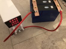
(y)(y)(y)(y) guys, you were right! I crimped up some thicker cables with ring terminals and immediately the PSU jumped into the C mode! But: it also started singing! It makes a really high pitched sound. Reducing the amps reduces the sound so I am guessing pushing 10A is pushing the PSU to its limits!

Thanks for the advice though! Much appreciated!
lifepo4-detail4.jpg
 
Inductors sing, also capacitors and other parts.
I boosted the switching frequency of my VFD from about 4 kHz to 15 kHz which quieted it down.

Glad it's working better.

One more improvement, although pretty minor at 10A with fat busbars, is to connect supply cable to far end of one busbar (opposite corners of the paralleled set of batteries.)
That matters more with parallel strings in the final application, running at high current.
 
I've got a simple 4S 100Ah battery sitting on my table, waiting to be top balanced for the first time. I am a novice when it comes to this stuff, but I've done a lot of reading and researching and have downloaded the Tutorial about balancing LiFePO4 with a 10A power supply. I think I have a good grasp of the important concepts but I am not sure if I'm doing everything right, though...??

The individual cells each measured in at 3.30v and I've hooked them up in parallel. I've decided not to do the pre-charging but instead go straight to the balancing. So I've taken the following steps:
- set the max voltage of the PSU to 3,65v (nothing connected)
- attached the positive (+) and the negative (-) clamps together to then dial in the amps (set to 10A)
- only after that is done clamp to and connect the battery terminals

...the PROBLEM (if it is one): the PSU display shows that the PSU is in the CV (constant voltage) mode, the display shows a permanent 3,65v and the amperage has dropped to around 4,0-4,2A and seems to slowly slowly decrease over time.

Now I'm really wondering whether this is correct?? I thought LiFePO4's needed to be charged up to 3,65v with a constant current?? Whats happening therefore seems to be the exact opposite. Or am I misunderstanding?
 
@powerB if the power supply is rated for 10 amps try running it at 8 or even 6.6 amps.
Cheap power supplies may not last long at their rated current.
 
Inductors sing, also capacitors and other parts.
I boosted the switching frequency of my VFD from about 4 kHz to 15 kHz which quieted it down.

Glad it's working better.

One more improvement, although pretty minor at 10A with fat busbars, is to connect supply cable to far end of one busbar (opposite corners of the paralleled set of batteries.)
That matters more with parallel strings in the final application, running at high current.
I've gotto admit that I don't know what "switching the frequency" of a VFD from 4kHz to 15 kHz means... but I have a feeling that would mean opening the divice to make that sort of a change. If the cheap Amazon device I have would even allow for that.

But good point on connecting the leads to the opposite ends of the battery pack! Thanks
 
Can I ask why join the leads togather and setting the voltage?
I did mind not so long ago with a similar Power supply ,
I couldn't get the reason why to connect the leads ,
I just connected a meter to the leads , turn the current up a little and set the voltage to read 3.65 at the meter , then connected the leads to the batteries and turned the current up as far as it would go , in my case 5.2A
So why do people connect the leads togather? What different does it make?
Many roads lead to Rome...
The manual of my power supply unit say to set the values according to those steps. It lets you dial in the voltage and that is reflected on the LCD screen but if you just turn the amperage knob the LCD screen shows no change. Only when you "short" the leads do you see the amperage value as you turn the know. You connecting your multi meter essentially does the same/similar thing
 
Can I ask why join the leads togather and setting the voltage?
I did mind not so long ago with a similar Power supply ,
I couldn't get the reason why to connect the leads ,
I just connected a meter to the leads , turn the current up a little and set the voltage to read 3.65 at the meter , then connected the leads to the batteries and turned the current up as far as it would go , in my case 5.2A
So why do people connect the leads togather? What different does it make?
It makes very little difference if any for this application. The reason is the IR of the cell is so low the power supply sees the current the same way as if shorting the leads of the power supply. The most important part is to always set the voltage before connecting the power supply to the cells. Then connect the power supply to the cells and adjust the current.
 
Back
Top