Rapidrob
New Member
As I've posted on this forum, I just built two identical 39120S battery packs.
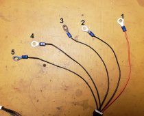
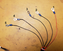
Each one producing about 13.2 VDC. The charging cables showed up today. 5 wire.
I hooked up the ISDT Air8 battery charger after hooking up the wiring to the Positive out put terminal and negative output terminal as well as three buss bars.
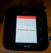
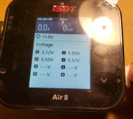
The charger throws out an error in a second or two " Abnormal Cells Voltage". I was able to take a photo of the instant I hook up the cable going to the cells for charging and you can see cell 1 on the lower left is 3.13 ( the red positive wire is on the out put + terminal, and one wire it on the negative - output terminal.) and the rest are 5.55 VDC, where the buss bars are. The charger is seeing these buss bar batteries as an abnormal battery voltage.( 6 VDC )
How do I hook up the 5 wires while the batteries are in the pack to be charged?
Please help.
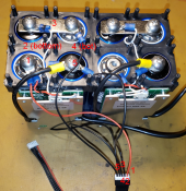
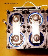
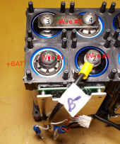
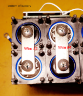
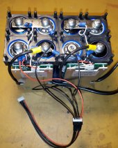
Bottom of battery pack. Top two wires marked in silver 2 & 3 for charger cable. Other two wires are for BMS sense wires.
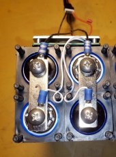
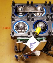
The red wire is on the lower left battery and the black is on the lower right battery terminal.
Disregard the 2nd battery pack on the right of the left four batteries.
The silver marked terminal is number 1 of the buss bar batteries.
Thank you for your help.
Each one producing about 13.2 VDC. The charging cables showed up today. 5 wire.
I hooked up the ISDT Air8 battery charger after hooking up the wiring to the Positive out put terminal and negative output terminal as well as three buss bars.
The charger throws out an error in a second or two " Abnormal Cells Voltage". I was able to take a photo of the instant I hook up the cable going to the cells for charging and you can see cell 1 on the lower left is 3.13 ( the red positive wire is on the out put + terminal, and one wire it on the negative - output terminal.) and the rest are 5.55 VDC, where the buss bars are. The charger is seeing these buss bar batteries as an abnormal battery voltage.( 6 VDC )
How do I hook up the 5 wires while the batteries are in the pack to be charged?
Please help.


Bottom of battery pack. Top two wires marked in silver 2 & 3 for charger cable. Other two wires are for BMS sense wires.

The red wire is on the lower left battery and the black is on the lower right battery terminal.
Disregard the 2nd battery pack on the right of the left four batteries.
The silver marked terminal is number 1 of the buss bar batteries.

Thank you for your help.


