diy solar

diy solar

Battery(300) Design Open Sourced

The Fustion 360 file I included is fully parametric, your son should be able to change the new cell dimension with a few clicks. see the screenshot below.
Yeah he's a wiz with the printer. Made me a RV bathroom cabinet latch that broke
He printed one from scratch. I'll post the progress when we get something
 
Son got one of the cell holders printed. Now to take the battery apart to see how it fits.
 

Attachments

  • PXL_20220220_161328015.jpg
    PXL_20220220_161328015.jpg
    357 KB · Views: 48
Ran into a snag. My terminals are too wide changing the parameters completing messes up the case parameters. My terminals are 25.4 mm from stud center to edge
 

Attachments

  • PXL_20220220_221631137.jpg
    PXL_20220220_221631137.jpg
    120.2 KB · Views: 46
Ran into a snag. My terminals are too wide changing the parameters completing messes up the case parameters. My terminals are 25.4 mm from stud center to edge
You need to adjust this parameter. looking at you picture, seems like the 'stool' on which the FR4 firewall sits needs to be narrowed a bit.
Hope this helps.

Screen Shot 2022-02-20 at 3.21.40 PM.png
 
Right, that's the parameter we changed we set it to 26mm. We got some errors, the walls of the case disappeared and the nubs that the lid sit on didn't change. My terminals might just be too far apart for the design to accommodate for.
 
Ran into a snag. My terminals are too wide changing the parameters completing messes up the case parameters. My terminals are 25.4 mm from stud center to edge

Thats probably due to the different terminal spacing between the 'old' LF280 cells and the new LF280K cells.
 
Right, that's the parameter we changed we set it to 26mm. We got some errors, the walls of the case disappeared and the nubs that the lid sit on didn't change. My terminals might just be too far apart for the design to accommodate for.
So in that case, just play with the parameter won't help as it's outside the range that parameter was designed for . However you can ask your son to adjust the design by doing one of the following

1. narrow the stool the firewall sits on, it doesn't need to be that wide. I think 8-10mm should be enough to accommodate a 3mm screw.
2. move the stool from center to an offset to avoid the terminal

Hope this helps, this is local change of the overall design, you can still reuse most of the design.
 
Well i finally printed my first draft .3 layer case fitment copy of cell case component in silver Sunlu PETG with a case thickness of 3mm, inspired by sunrise's model.

IMG_1040.jpg

I still have to chamfer edges and clean up my file to sort out my tolerances, but a huge thanks for Sunrise, for letting me review the timeline so i could work out how to model my own design in Fusion 360 heavy influenced by his design.

I must say, while i've used user parameters to allow adjustment, my model is quite flawed in being able to be adjusted, but i'm finding work arounds.

Still awaiting some of my fittings to turn up to measure, and i've got to model in some locating pins for the cases.

My case is a little too tight at the bottom, so i have to adjust that without everything moving around ?

the top support needs a little more thickness, as i cracked it when cleaning out some supports, the print quality will be better on the final version, as i plan on printing .2 layers and in quality mode.

Although i have modelled a firewall like Sunrise, so i don't really need this top support, it was more for printing, the firewall will tie it together along with the lid of the case
IMG_1039.jpg
 
Well i finally printed my first draft .3 layer case fitment copy of cell case component in silver Sunlu PETG with a case thickness of 3mm, inspired by sunrise's model.

View attachment 85744

I still have to chamfer edges and clean up my file to sort out my tolerances, but a huge thanks for Sunrise, for letting me review the timeline so i could work out how to model my own design in Fusion 360 heavy influenced by his design.

I must say, while i've used user parameters to allow adjustment, my model is quite flawed in being able to be adjusted, but i'm finding work arounds.

Still awaiting some of my fittings to turn up to measure, and i've got to model in some locating pins for the cases.

My case is a little too tight at the bottom, so i have to adjust that without everything moving around ?

the top support needs a little more thickness, as i cracked it when cleaning out some supports, the print quality will be better on the final version, as i plan on printing .2 layers and in quality mode.

Although i have modelled a firewall like Sunrise, so i don't really need this top support, it was more for printing, the firewall will tie it together along with the lid of the case
View attachment 85745

Very nice work, @bryn
I can definitely appreciate the hard work behind this, as I went through this process just a couple of years ago.

Some feedbacks -
1. I noticed the section of rod tunnel is square, there are 2 downsides of this - a) it uses more material, takes longer to print, without gain extra strength. b) the sharp turn is not printer friendly as the step motor needs to work much harder at these 90 degree turns
2. The rod seems to be a bit too thin, it might flex.
3. PETG might not be necessary - it prints a lot slower on my printer, I only used that for the vent cover.
4. The key to parametric model is to have *fully constrained* sketch.

Look forward to your next iteration.
 
Thanks sunrise,

This is my second attempt on modelling this case, the first model wasn't worth unpicking and fixing and i hadn't used user parametrics, but it helped get my head around a few things with fusion, That you tube link was handy, i learnt a lot from that learn fusion in 30 days. although i only got to day 19 and then i could help myself working my second model.

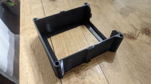
The square rod tunnel will be chamfered, i just hadn't reapplied them after i changed a few fixtures in the model, i'm just waiting for a few more fittings to turn up to get correct dimensions to insert them and then re apply the chamfers.

I agree with you on the rod, strength wise its fine, but i couldn't find any room for M8 with the size of my print bed on the Prusa, i've got about 1.5 mm left and the slicer has issues with the path.

I've got a fine tolerance in the hole, there isn't any slop at all, i did add an extra mid rod to help with twist, i guess ill see at the end, but i have high hopes that it will be ok.

I did consider not using PTEG, but i really needed the mechanical properties, as we do a lot of off road travelling, corrugations just destroy everything, i'm hoping the extra flex in PETG with handle it, another issue is heat, so i figured PETG would be better for me.

So far i've printed just over 120 hours of PETG, i haven't had an issue "yet" and the prints have been super clean and i had already ordered 5 rolls of it.

I spent a lot of time, getting the first layer tuned in, and my benchies turned out great with Prusa PETG, this SUNLU isn't as good, but hardly any stringing, and its $25 a roll compared to a $80 Prusa roll. so i'll keep fine tuning it.

i was quite surprised, but it prints really well, this trial piece is the roughest print i've done, but i had it in draft mode to run it and see what the draft mode looked like.

I have been drying it and running it through a filament dryer while printing, that may have helped, i don't know, but our humidity has been between 70-90% over the last few weeks, so the dryer must be helping.

you are right about the "Fully Constrained" aspect, mine is mostly constrained, but i noticed this morning when reviewing my model to find out what was going on, i had applied the constraint points on the wrong part of the model, so it wasn't moving correctly what adjusting parameters, i just didn't think ahead at the time.

I'm learning more as i go, and finding flaws that i did earlier, i've spent so much time troubleshooting why i have an issue and finding a way to resolve it, but this has been fun and frustrating.

304 Battery Case v52.png

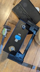
I designed the firewall to hold the BMS, utilising the heatsink holes in the BMS, i also have the battery fuse block within the front section of the case under the terminals, the battery itself is compressed, i designed the front case to have coupler nuts, so i can screw the front cap on to access that without uncompressing the pack.

i'm up to v68 at the moment, once i fix up my parametric issues, ill work more on the firewall to allow for grommets for cabling and my current drawing has a split lid to work with my printing bed limitations.

I learnt a lot from just making a battery terminal component from the technical specs, to insert into the battery.

I was tempted to use your file and adapt it, but at the time i didn't even know how to adapt it. so i reviewed the timeline and how you used your user parametric for each component to see how you applied them.

I even took printed out a screenshot of the your user parametric's on how you labeled them to review when putting user para in my drawing. it didn't make sense at the beginning, but once i'd written them in my battery terminal model, it all made sense.


I'll most likely spend another few weeks on the drawing, as i want it fully dialled in before i print it, and i have a fair bit of printing to do while i finish the drawing, i got a few ASA external parts i need to print for my camper, once i've finished modelling them in fusion and then i want to try printing a few things in PLA before i smash out all the case parts.

I'm just amazed by 3D printing, i've got my own industrial woodworking workshop that i handcraft modern fine furniture in, i should have made the jump to 3D printing a long time ago, for miniature modelling of furniture instead of by hand, i've always just drawn 1:1, 1:10, eta scale drawings by hand and worked the way i was taught.

Thanks again for your help
 
Very nice work and thanks for contributing.

What kind of therminal posts/blocks do you plan to use?
1646856901071.png

Found this interesting video about it:
 
Last edited:
Just an Update, and to Bump up Sunrise's Thread to try and get people to give 3D printing a go.

Well, i couldn't fix my V2 file, My constraints were linked all over the place and i wasn't able to resolve them, so i just started a new Model, it was quite quick to do a new model, It's better constrained than the last one, not perfect, but its ready for printing, i did a trial of a cell case and it worked, i found a few faults in it, which i fixed up for the first real case.

I have to clean it up a little, i used the Fuzzy feature on Prusaslicer to give me a dimpled effect on the case and iron feature to put a clean straight edge the top edge, i really like the textured result, and it works with this PETG, I have to admit, it took a far bit of tuning to get get a reasonable finish with this coloured PETG, the Black SunLu PTEG was great on generic settings and of course the $$$ Prusa PETG i got with my printer prints like PLA

So fair i've managed to print stuff in ASA, and TPU without issue and I can see why everyone uses PLA/PLA+, its so easy to print and the finish is amazing

Now i just have to keep printing 24/7 to get it finished.


IMG_1061.jpg
 
Wow that is a nice finish. I've only managed PLA (works well) and clear PETG with the simple layered looking finish. I've also found it interesting how the different colors print differently. Nice results.
 
@sunrise
Just wanted you to know that this thread inspired me to actually buy a 3d printer.
I've wanted one for years, just never felt like I'd use it much, but that's all changed now!
Thanks for the inspiration!
 
@bryn
When your done do you think you could share your design? Looks like you have the same issue with the studs being out closer to the edge as I do. I would redesign myself but son is the one with the printer and I can only ask him to print and not to take his time adjusting for me.

But this might be time for me also to invest in my own printer.
 
Wow that is a nice finish. I've only managed PLA (works well) and clear PETG with the simple layered looking finish. I've also found it interesting how the different colors print differently. Nice results.
Thanks, I did over 18 different cubes to get the finish i liked, and different temps to reducing the stringing. but i like how texture works, i've got no stringing that i've found and only the odd zit in the internal corners.

I noticed Cura also offers the Fuzzy mode.

It's just a shame, in Prusaslicer that you can't paint the surfaces you want to have the texture, its either outside faces or all, which is annoying as i'll have to split my lid to able to print it and i can't stop the connecting edges to be clean.
 
@bryn
When your done do you think you could share your design? Looks like you have the same issue with the studs being out closer to the edge as I do. I would redesign myself but son is the one with the printer and I can only ask him to print and not to take his time adjusting for me.

But this might be time for me also to invest in my own printer.
I have no problems sharing the design after i've tested it and if it all works as it should, after all it was Sunrise who started me on this rabbit hole of a project.

Although it isn't as refined as Sunrise's Model

I'm not sure why some of us have different distanced studs, it almost caught me out as the spec sheet had them the same as Sunrise's cells, but it was an easy fix.

I'll have a look at sunrise's file and see if i can adjust it and see if i can make it work for your cell, what is the shoulder height on your cells? 200-203mm? my stud centre is 25mm from the edge, i'm guessing yours is as well.
 
Hi jdfrye, I tried to adjust Sunrise's file for your Cells, but i don't have the skills to edit it to work.
 
Back
Top