diy solar

diy solar

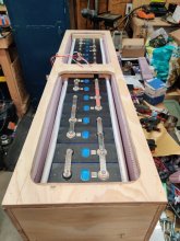
Battery Box Build

The source I used for my warming pads said that RV water tank heaters are the wrong type to use for batteries. They'll get too hot. RV water tank heaters are based on heating a plastic tank with water in it. You have metal cell walls with electrolyte inside.
I was originally planning to use the exact same RV heating pad you had used in your heater. After seeing the issues you had I reverted back to one of the alternate plans I had. Im now using the same thermostat you had promoted in your thread but am using 4 120W silicone heating pads instead. The two on either ends of the bank will be wired in series so each of those pads will be good for 30W and then two in the middle can be off or on with the outside two and will be switchable series or parallel so If its -30 out and I have let it everything cool down but decide to go out on short notice. I can switch them to parallel and heat everything up a lot faster.

These are the pads I have on order: https://www.amazon.ca/gazechimp-Sil...w+silicone+heating+pad&qid=1612496540&sr=8-25
 
Heating a battery fast may not be a good idea.

I had zero problems with my heating pads. The entire problem was with the thermostat that came with them. It was independent of the pads, so it was easily substituted.
 
Heating a battery fast may not be a good idea.

I had zero problems with my heating pads. The entire problem was with the thermostat that came with them. It was independent of the pads, so it was easily substituted.
Fast is relative. They are still thermostatically controlled and there will be an air gap between the batteries and aluminum plate the pads are under so its not like Im trying to pour a steady 300W of heat into the cells all at once. The idea right now is to set the thermostat to -15C or so for longer term idle periods when not in use but when I am going to take the truck out, turn it up to 10C.

I dont know for sure and 300W may be way too much power and the thermostat may be cycling constantly. Series connecting the center 2 and limiting the second 2 and limiting total output to 120W may be required and possibly 60W will be all that is usable. Not sure at this point, just trying thing out to see what works.
 
Looks great! I've not followed all the details but, are you heating from the bottom or the sides?
 
Looks great! I've not followed all the details but, are you heating from the bottom or the sides?
Bottom only, each box has it's own heating pad. I added a HDPE spacer between the pads and the bottom of the cells.
I'm thinking I'm going to keep the bus bars for the pairs of cells, but add flexible pairs of 2awg jumpers to connect the pairs instead of the small bus bars.
 
Bottom only, each box has it's own heating pad. I added a HDPE spacer between the pads and the bottom of the cells.
How thick is the HDPE? I thought I saw you considering aluminum plate at one point. Bottom makes sense to me.

I saw on another battery box thread the idea of a thicker VHB tape vertical run where the cells meet that I really liked as to me it accomplished 3 things: allowing heat to flow up and around the cells, allowing the cells a fractional amount of room in which to expand (on that thread it was discussed that a tiny amount of allowed expansion is good.), and securing the cells in the group firmly which for a vehicle application appeals to me in protecting the terminals.
 
The manufacturer specs said not to mount to metal - likely to prevent shorting. The hdpe is .187 thick.
12x24 pieces were about $15 each from amazon.
 
The manufacturer specs said not to mount to metal - likely to prevent shorting. The hdpe is .187 thick.
12x24 pieces were about $15 each from amazon.
Did you put anything between cells too or is the blue film is enough?
 
Any reason you went the long way instead of a wider box for side by side? Also, has anyone lokked at using marine double battery boxes?
 
Any reason you went the long way instead of a wider box for side by side? Also, has anyone lokked at using marine double battery boxes?
Ayup.
1) I wanted an even weight distribution across my camper. I chose the layout to optimize for that. I have a bay up front where this will work nicely.
2) Limiting the length of jumpers between cells is important - anything over 15cm has too much inductance and will cause issues with balancing. Between the two boxes and two layers of insulation, that's 4.5 inches (11.43cm) before you add in the distance to the terminals. To use a side to side layout, I'd have to modify the box design.
 
Following, fellow 5th wheel traveler here too. Currently have 8 Xuba 280Ah 4s2p 12v config looking to do something like this. I might have missed it in another thread but how are you connecting to your 5th wheel electrical?
 
Following, fellow 5th wheel traveler here too. Currently have 8 Xuba 280Ah 4s2p 12v config looking to do something like this. I might have missed it in another thread but how are you connecting to your 5th wheel electrical?
This should be useful for you: https://diysolarforum.com/threads/changes-to-my-build-after-this-summer-fall-of-usage.16962/
24v battery, using a 24/12 70a converter now. Old 12v FLA is gone, I added a breakaway SLA and charger to run the breakaway brakes.
 
This should be useful for you: https://diysolarforum.com/threads/changes-to-my-build-after-this-summer-fall-of-usage.16962/
24v battery, using a 24/12 70a converter now. Old 12v FLA is gone, I added a breakaway SLA and charger to run the breakaway brakes.

That brings up an issue I've been thinking about for the past few days. RV trailer owners that eliminate the SLA battery and add a DC-DC charger between the 7-pin and the LiFePO4 battery bank are going to have a problem with the breakaway system. If the 7-pin cable becomes disconnected, there is nothing there to provide power to the breakaway system. The DC-DC charger functions in one direction, towards the LiFePO4 battery bank.

To work around that, a new wire from the LiFePO4 battery bank has to be run back to the breakaway system.

7-pin -> DC-DC Charger -> LiFePO4 -> Breakaway System

It's something that I'll be on the lookout for when reviewing proposed systems.
Adding a $20 SLA and a $5 charge controller solved this for me. My victron battery monitor has an aux battery voltage monitor that keeps an eye on it.
 
Adding a $20 SLA and a $5 charge controller solved this for me. My victron battery monitor has an aux battery voltage monitor that keeps an eye on it.

In my case, before my LiFePO4 upgrade, I had solar to charge the SLA bank on the tongue, so I retained that. The tongue SLA is also responsible for starting the generator. I need to reconnect the old AC-DC converter so that it charges the SLA battery while the generator is running. One more task to complete once the weather warms up.
 
Any reason why you wouldn’t simply connect your breakaway to your main battery bank? Accessibility?
 
Back
Top