diy solar

diy solar

BattGO Wiring

I was tracing the wires from my homemade wiring harness to the adapter. I guess I do have a wiring issue. When I plug the Battgo in, I have been clipping the ground wire to the negative. if I leave the ground off, the number eight wire shows nothing, when I plug it in that is the one that reads really high. I'm just not sure what I did wrong. When I use the voltmeter everything is ok at the connectors. I still get 29 volts on the Battgo and 26
with the voltmeter. The pins still start at 3 and go by threes until the last pin is 26. I just thought I would update. I guess I need to redo the harness. Buying that 10 pack of wire connectors was a good idea.
 
Yea, I'm with jasonhc73, a good picture showing the wiring as much as possible.

Also, happen to have a pic that shows how the batteries are wired?

As far as I know, you are the only person who has this kind of issue with a BattGo.
Maybe its time to get a replacement sent (hopefully it involves amazon prime).
 
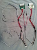
I have two BYD Batteries wired as 48volts. When I use the BattGO I have to disconnect the one cable so I have two 24v batteries to hook my two harnesses to. The adapter shows the voltage going up by threes until 26v. I got two nice cables with the adapters but they have small ends where one fits into the adapter that one fits I guess fit into a BMS. So I couldn't use them and left them alone. The BattGO harness has 9 wires so I used the one as a ground wire. I admit something ain't right. I spent the money on these two adapters so I didn't have to cut and solder the wires to the battery harness. The confusing thing was having eight wires coming out of the adapter and nine wires on the BattGO connector.
20200420_102929.jpg
 
The BattGO harness has 9 wires so I used the one as a ground wire. I admit something ain't right.
I'm not convinced a 8s monitor can be used on every other cell on a 16 cell 48v battery, but...

The 9th wire (its actually considered wire #1) is not for a "ground" but rather needs to be connected to the negative post on cell #1 (which is the negative end of the cells in the battery). And then, assuming this works with 16 cells, the 2nd wire would go to the positive post on cell #2. 3rd wire on cell #4 ...
This would in theory increment the voltages at about 6.4v in the same progression.

Sorry i am not familiar AT ALL with the BYD wiring to comment on the wiring pictured. jasonhc73 is the authority on this from what i have seen.
 
The batteries are 24 volts each when disconnected as I stated.
 
I did write that I had to disconnect a wire so I could hook up to 24v. The second sentence. I'm trying to check cell balance and balance them on occasion.
 
Ok, sorry, i only have what you say to go by.

So the questions seems to be what to do with the 9th wire on the connector?
Wire #1 NEEDS to go to the negative on cell #1. I have no idea if there is a wire for that or even if the cells are accessible but that is where the BattGo NEEDS to be connected.

And I'm sure you've been thru this enough time to switch what i said earlier with leads going to each cell for your 24v battery. Wire #1 to cell #1 negative... wire #2 to cell #1 positive...
 
Are the 8 wires on your 8s wiring harness connected to the + terminal of each of the 8 cells? If so, you will need a wire to cell 1 - terminal to adapt to the 9 wire BattGO harness.
On the connector, position 1 is the negative terminal of cell 1, position 2 is the positive terminal of cell 1. The voltage between these should read around 3.3v.

Position 3 is the positive terminal of cell 2. The voltage between position 1 and position 3 should read about 6.6v.

Position 4 is the positive terminal of cell 3. The voltage between position 1 and position 4 should read about 9.9v.

Seeing the pattern here? Voltage difference from position 1 and position 9 is the voltage of the entire battery.
Which are you calling cell #1?

Would it be the cell with your main pack negative or your main pack positive?

Also, is this "negative" lead the one on the BattGO that has a circle with a dash (negative) in it and an arrow pointing to a wire. I know that question may sound retarded, but my first two wires on the other end are black then red.
 
I decided to put off making the battgo work for now. it's stored for now and soon will power up my small home. The pins are correct. Thanks for the reply.
 
I decided to put off making the battgo work for now. it's stored for now and soon will power up my small home. The pins are correct. Thanks for the reply.
you might want to check this video out.....it is possible to calibrate your ISDT Charger.

 
you might want to check this video out.....it is possible to calibrate your ISDT Charger.

That's interesting, I had never seen that. And for the moment that I actually got mine to power on by some partial correct lead connections, I could see it needed just that.
Still, my problem is connecting correctly to an 8S Lifepo4 in the first place.

As I mentioned, following @MisterSandals instructions isn't as easy as it sounds. It doesn't explain which cell IS cell #1. At which end of the pack is it...the main negative cell, or the main positive cell?

Like I said, I had at one time, following @mister connected
 
I feel like I've tried several scenarios and none make this thing even power on.
Connecting to cell #1 (main battery positive), using as the negative connection on that cell the lead from the BattGO with the arrow/dash marking, then the adjacent wire to the left connecting to that same cell's positive terminal...then going down the line to the left connecting each wire to the next cells positive terminal... nothing happens.
 
Sorry i missed this.
Cell #1 is the main negative end of the battery.
Wire 1 connects to cell 1 negative. Wire 2 to cell 1 positive. Wire 3 to cell 2 positive... continue thru all positive posts.
Got it. Mine happens to have a black wire, but it is at the opposite end of the harness from the circle with a neg symbol in it and an arrow on the BattGO. So should I ignore the black wire in my case, and use the one inline with that symbol?
 
It's a tremendous help, wish I had it some time ago...it should be in the resources section.
I wish I'd had it sooner, I think mine may be busted now after trying various configurations to figure this out. When I hook it up nothing happens. But when I connected it this way initially it though my battery was a 7S and only showed 7 cells voltages...and not accurately at that. Wonder why that might be. Seems like others have had similar problems, but I've never seen their resolution.
 
Just created the diagram a few minutes ago, otherwise would have posted it earlier.
If you are connected properly, yet the device does not power up, it may have been zapped as you suspect.

When connecting to the BattGo, it seems the Pin1 black wire should make contact first (by sort of angling the connector when attaching). Otherwise, something inside pops. Perhaps an internal fuse, but the thing is not easy to open up to check or fix. Did you hear a "pop"?

Did you buy it on Amazon by chance? If so, replacement should be fairly painless.
 
Also, did you set the device to your battery type? I think it defaults to Li-Po (Lithium Polymer). Not sure, but perhaps that had something to do with the odd readings you were getting on a Lifepo4.
 
Just created the diagram a few minutes ago, otherwise would have posted it earlier.
If you are connected properly, yet the device does not power up, it may have been zapped as you suspect.

When connecting to the BattGo, it seems the Pin1 black wire should make contact first (by sort of angling the connector when attaching). Otherwise, something inside pops. Perhaps an internal fuse, but the thing is not easy to open up to check or fix. Did you hear a "pop"?

Did you buy it on Amazon by chance? If so, replacement should be fairly painless.
You know, I may have heard that pop. I most definitely could have fried it (although it never stopped while tinkering). I got frustrated and started connecting it every which way but loose. Guess I figured I had 35 bucks. I did get it on Amazon but procrastinated for a while because I then found I needed to make my own harness, and researched that forever. Ordered that stuff and made it, then couldn't find exactly how to connect. There is sooo little clarity from the manufacturer or forums on how to get started with these. You might get rich if you make a 24v Lifepo4 how to video. Now, looks like my timeframe for return expired a few days ago.
I did notice, while it was sort of working, that it said LiPo and switched it to LiFe, and it made more sense after that...but still wasn't quite right. Voltages were off quite a bit and missing one as a "7S".
I wouldn't need the BattGO at all if the current BMS options weren't the most unreliable, confusing and unestablished apparatus in the world.
 
If it's dead in the water and you can't return it, it's a good candidate for prying open to inspect for a blown fuse maybe. The face must be removable.
 
If it's dead in the water and you can't return it, it's a good candidate for prying open to inspect for a blown fuse maybe. The face must be removable.
It's Alive!!! Thanks man, your diagram saved the day. Question, what happens if you connect two packs in parallel, but one is at 3.337 SOC and the other is at 3.7 SOC? Too big of a gap, too much heat transfer? Could something get too hot too fast and damaged?
 

diy solar

diy solar
Back
Top