diy solar

diy solar

Beginning a Victron ESS for self consumption - correctly rated fuses and cables?

mrdiy

New Member
Joined
Oct 26, 2022
Messages
6
Hi all, I found a bargain ebay purchase and trying to make an ESS for self consumption.

I have a background in IT and some engineering, but admit I'm a complete noobie. This is new to me and I want to be safe. Here's the proposed setup:
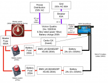
Possible ESS Setup.png

I have a Victron Quattro 24v 8000VA (6500w rated) inverter (datasheet of specs attached). My energy provider offers cheap tariffs at 1/3 of the day rate price (so its 12p per kwh from 11pm to 5pm). I want to charge batteries at night then use through the day. I've seen some 304Ah batteries on sale (datasheet attached). I only have the inverter right now and have been researching for past few weeks but confused here and there. Not sure if I've spec'd out a safe and reliable system that will meet my needs. Any help would be appreciated :)

My thoughts - am I on the right track?:
  1. Overall ESS Setup Summary:
    1. 8s2p battery bank consistes of two packs of cells, connected via 50mm^2 battery cables cut same length
    2. Each battery pack fused with class T/ANL fuse of around 250A
    3. JK 4s-8s 200A BMS on each battery pack.
    4. Victron 500A smartshunt added to negative terminal of inverter and all battery pack negatives connected directly to that
    5. Main DC system fuse of 600A
  2. Capacity:
    1. 12kwh daily use => 304Ah battery capacity x 16 cells x 3.2v = 15.5kwh capacity => about 3kwh spare so i drain to 20% SOC everyday to keep battery healthy.
  3. Battery packs:
    1. Each battery pack would be 8 in series so its two packs in parallel e.g. 8s2p. This would give 24v and 608A max (currents add up but voltage stays same).
  4. Current draw:
    1. Inverter can run continuously at 6500w => 6500 / 24 = 270A total rated current draw. If I keep battery leads the same length, can I assume its (270/2) = 135A that will be drawn from each battery pack?
  5. BMS:
    1. Victron inverter has protection capabilities but from watching off grid garage and will, etc it seems better to have a BMS. Not sure if it needs to be active or passive but JK BMS seems right way to go (maybe Daly or passive thing like Helltec). To be safe I'm leaning on the idea of a JK BMS (JK-B2A8S20P 4S-8S 200A) on each battery pack.
    2. From off grid garage channel I've gleaned to bulk charge upto 3.45v then it should go into absorption for half hour or so after that as not to overcharge (eg charge quickly to 80% then let it trickle charge up the rest of the way).
    3. A part of me thinks I only need a passive balancer as its cheaper and only needs to top balance the battery cells when its over 3.45v - thoughts?
  6. Charging:
    1. Factors and assumptions:
      1. 15.5kwh capacity,
      2. Victron 24v battery charger with 200A capability
      3. 230v mains (with 80A grid connection fuse)
      4. JK BMS with 200A cutoff
      5. 6hours of off-peak electricity
      6. Victron limit charging to 75% of rated power => 6500w x 75% = 4875w => 4875w / 24v = 203A (in specs it says 200A)
    2. If the factors and assumptions are correct (assuming battery fully depleted) so 15500 wh / 4875w = just over 3 hours to replenish batteries at full charge.
    3. Another factor is what is a healthy charge rate of the 304Ah batteries? On the spec sheet (see attached - who knows if its credible) it says they are tested at 150A charge and discharge rates. On off grid garage channel, he charges and discharges (i think) around 40A. Not sure what is healthy, safe and realistic charge rate should be here?
  7. Protection:
    1. Inverter can peak at 16kw and continuous at 6.5kw. I'll run just under the continuous rating but due to electrical surges in appliances and motors etc (washing machines, electronics, etc switching on) I'm guessing I should fuse for peak so 16000w / 24v = 667A. Would a 600A fuse suffice to act as main fuse on positive entry to inverter to cut everything off and cables burn?
    2. Lynx distributor seems to be neat and use mega fuses - do I need it in my setup? I was thinking i connect directly to terminals on switch or shunt. In future I do want to add an MPPT but maybe only one.
    3. The JK BMS appears to cut off at 200A, 50mm^2 battery/welding wire is rated at 345A, battery pack current draw is 135A per pack (if parallel working assumptions are correct from #3) => 250A ANL fuse for each battery pack should suffice?
    4. Alternatively I can use DC solar breakers that are 250A but are high DC voltage - will they work for battery protection better to stick to switch and fuse combo?
    5. On a youtube forum it was recommended by 'TTSmith' that Schneider INS250 should be used to prevent DC arc'ing and welding.
    6. Most people say to use class T fuses as the main fuse but the Victron lynx shunt itself uses cheaper ANL fuse. I'm confused if there's really a benefit for home ESS to use more expensive class T. I'm not using a Lynx shunt (they're so expensive but grudgingly will use class T - any concise thoughts? (I know that is a huge topic).
  8. Monitoring:
    1. I have an old tablet that will be mounted alongside the setup to connect to VRM
    2. JK BMS can be bought with small LCD screens not sure if I need this as I can bluetooth in from the tablet
If you made it this far then thank you - I dearly look forward to hearing your thoughts.

I've probably made some errors in here and missed some things out. Please be patient with me :)
 

Attachments

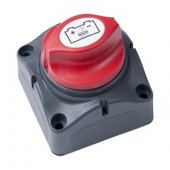
  • battery switch 275A.jpg
    battery switch 275A.jpg
    17.7 KB · Views: 9
  • PBRC- LF304-S01-LF-《LF304电芯产品规格书》-C版 7 12.pdf
    3.4 MB · Views: 2
  • Datasheet-Quattro-3kVA-15kVA-EN.pdf
    439.5 KB · Views: 1
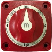
  • blue sea master switch.jpg
    blue sea master switch.jpg
    34.2 KB · Views: 9
Last edited:
For next life charge between 0.25C and 0.5V. Avoid any form of long term low current charging under 0.15C. Do not float or trickle charge LFP for best life cycles.

Given you have a battery based grid tied system. Your system components must meet U.K. G98 and must meet various codes and anti islanding protecting.

You will also need permission from your DNO as you have a battery system.

Your AC must meet the relevant standards


From the outset, the designer and installer of a PV system must consider the
1.3 Safety
Photovoltaic (PV) Power Supply Systems (ISBN 0 85296 995 3, 2003)
G IEE Guidance Note 7 to BS 7671 - Special Locations, Section 12 Solar
parallel with public low voltage distribution networks
connection of small scale embedded generators (up to 16A per phase) in
G Engineering Recommendation G83/1 (2003) – Recommendations for the
the installation of these systems that are of particular relevance:
a PV installation. However, there are two documents which specifically relate to
terms, at the time of writing there is still relatively little which specifically relates to
is drawn from such requirements. While many UK standards apply in general
other relevant standards and Codes of Practice. Much of the content of this guide
Any PV system must comply with Health and Safety Requirements, BS 7671, and
1.2 Standards and Regulations”

I suggest you familiarise yourself with https://www.bre.co.uk/filelibrary/pdf/rpts/Guide_to_the_installation_of_PV_systems_2nd_Edition.pdf

Note that the Quattro is designed for recreational vehicles and not domestic solar and may not have the correct approvals.

The system may need professional installation or professional certification to allow it to be connected to the grid.
 
Last edited:
Hi all, I found a bargain ebay purchase and trying to make an ESS for my UK home (230v grid).


With 16 cells I would use a 48V system. So a 8000VA 48V Multiplus II for example.
Quattro is for double AC input like a generator. No need for that :)
Also one JK BMS is enough.


For next life charge between 0.25C and 0.5V. Avoid any form of long term low current charging under 0.15C. Do not float or trickle charge LFP for best life cycles.

And you are right, do not float an LFP battery :)
If the battery is full, charging needs to stop.

There is no problem if you only charge at 0,15C.
But it must be CC-CV charging


Given you have a battery based grid tied system. Your system components must meet U.K. G98 and must meet various codes and anti islanding protecting.

Except this is an off-grid (with grid support) system ;)

He does not want to sell to the grid.
And so no permission is needed from utility company.


Note that the Quattro is designed for recreational vehicles and not domestic solar and may not have the correct approvals.

Nope. Quattro and Multiplus II is INDUSTRIAL inverter. Many use it for bigger industrial systems too.


The system may need professional installation or professional certification to allow it to be connected to the grid.

If it would sell to the grid.
I do not know the local regulations but Off-grid can be installed at most countries without permission.
 
With 16 cells I would use a 48V system. So a 8000VA 48V Multiplus II for example.
Quattro is for double AC input like a generator. No need for that :)
Also one JK BMS is enough.


And you are right, do not float an LFP battery :)
If the battery is full, charging needs to stop.

There is no problem if you only charge at 0,15C.
But it must be CC-CV charging


Except this is an off-grid (with grid support) system ;)

He does not want to sell to the grid.
And so no permission is needed from utility company.


Nope. Quattro and Multiplus II is INDUSTRIAL inverter. Many use it for bigger industrial systems too.


If it would sell to the grid.
I do not know the local regulations but Off-grid can be installed at most countries without permission.
If your solar is above or below a certain size and has a AC connection , you must either inform your DNO or seek permission. It has nothing to do with “ selling to the grid “

To my understanding Quattro does not have relevant U.K. PV approvals.

In all cases G98 must be followed as well as relevant AC practices and this will require professional certification.
 
There is no problem if you only charge at 0,15C.
But it must be CC-CV charging

0.15C results in very slow charging offering more time for SEI layer degradation.

Where possible Li should be charged as fast as practical within battery specs, charger power constraints and temperature limits.
 
If your solar is above or below a certain size and has a AC connection , you must either inform your DNO or seek permission. It has nothing to do with “ selling to the grid “

In all cases G98 must be followed as well as relevant AC practices and this will require professional certification.

I know some EU country regulations and in most cases the Off-grid systems (under 50kW) do not need any permissions.

Also there is some confusion about the meaning of Off-grid
It has a history ...

40+ years ago Off-grid meant to be completely separated from grid.
35 years ago with the UPS systems it changed to: Load can get grid or inverter power
30 years ago with the Online UPS systems it changed to: Can not sell to the grid.

And many-many countries are stuck 30-40 years into the past.

The usual solution is to use double conversion.
Have a battery charger, charge battery from utility if needed, and inverter does not have AC_in connected to grid.
Its inner DC/AC inverter is working all the time, producing your own clean phase.


0.15C results in very slow charging offering more time for SEI layer degradation.

Where possible Li should be charged as fast as practical within battery specs, charger power constraints and temperature limits.

Interesting. I never ever saw a research that supports this.
Can you link the research please ?


But I saw many that say that higher than 40Celsius and lower than 0Celsius temperatures and high charging rates (like 3C) causes SEI layer growth.
And so capacity loss. Like this research:
 
8000VA ~= 6400 watts
6400 ac watts / .85 conversion efficiency / 24 volts low cutoff = 313.725490196 service amps
313.725490196 service amps / .8 fuse headroom = 392.156862745 fault amps
That is a big 24 volt system.

I suggest...

Making a your system look like a ladder.
Where the risers are busbars and the rungs are the circuits.

Get rid of the disconnect for the inverter circuit because its redundant to the battery disconnects.
Use 2x 70mm2 wire each with a 300 amp class-t fuse for the inverter positive wires as close to the busbar as possible.
That is what the manual suggests/requires on page 9 --

Get rid if the shunt as its pretty much redundant to the current accounting in the battery BMSs.
I know the cerbo integrates with the shunt but I'm not convinced its worth the bottleneck in this fairly simple setup.

Add a 3rd battery because you have the potential to pull very hard on 2 batteries.
Use 50mm2 wire with a 250 amp class-t fuse as close to each battery as possible.

Add a pre-charge circuit to prime the inverter capacitors to protect the BMSs.

Why not do a 48 volt system and half the amperage?
 
in the U.K. any PV install that has a battery and has a island capability ie can run without the grid but has a grid connect even if it does not export

Require prior DNO approval because of the danger incorrect islanding design can cause
 
Hello from someone else in the UK who’s also on a learning curve. Here’s a link to what I’m up to and my questions and challenges.

I also think that you WILL need DNO approval which I’ve yet to make sense of.
I found some certifications on the ENA for the Multiplus iI 3000/5000’s but not the 8000’s. However I”ve just read that they are NO longer compliant because of a change that was made early October. I could be stuffed.
 
Hi all, I found a bargain ebay purchase and trying to make an ESS for my UK home (230v grid).

I have a background in IT and some engineering, but admit I'm a complete noobie. This is new to me and I want to be safe. Here's the proposed setup:

View attachment 118314

I have a Victron Quattro 24v 8000VA (6500w rated) inverter (datasheet of specs attached). My energy provider offers cheap tariffs at 1/3 of the day rate price (so its 12p per kwh from 11pm to 5pm). I want to charge batteries at night then use through the day. I've seen some 304Ah batteries on sale (datasheet attached). I only have the inverter right now and have been researching for past few weeks but confused here and there. Not sure if I've spec'd out a safe and reliable system that will meet my needs. Any help would be appreciated :)

My thoughts - am I on the right track?:
  1. Overall ESS Setup Summary:
    1. 8s2p battery bank consistes of two packs of cells, connected via 50mm^2 battery cables cut same length
    2. Each battery pack fused with class T/ANL fuse of around 250A
    3. JK 4s-8s 200A BMS on each battery pack.
    4. Victron 500A smartshunt added to negative terminal of inverter and all battery pack negatives connected directly to that
    5. Main DC system fuse of 600A
  2. Capacity:
    1. 12kwh daily use => 304Ah battery capacity x 16 cells x 3.2v = 15.5kwh capacity => about 3kwh spare so i drain to 20% SOC everyday to keep battery healthy.
  3. Battery packs:
    1. Each battery pack would be 8 in series so its two packs in parallel e.g. 8s2p. This would give 24v and 608A max (currents add up but voltage stays same).
  4. Current draw:
    1. Inverter can run continuously at 6500w => 6500 / 24 = 270A total rated current draw. If I keep battery leads the same length, can I assume its (270/2) = 135A that will be drawn from each battery pack?
  5. BMS:
    1. Victron inverter has protection capabilities but from watching off grid garage and will, etc it seems better to have a BMS. Not sure if it needs to be active or passive but JK BMS seems right way to go (maybe Daly or passive thing like Helltec). To be safe I'm leaning on the idea of a JK BMS (JK-B2A8S20P 4S-8S 200A) on each battery pack.
    2. From off grid garage channel I've gleaned to bulk charge upto 3.45v then it should go into absorption for half hour or so after that as not to overcharge (eg charge quickly to 80% then let it trickle charge up the rest of the way).
    3. A part of me thinks I only need a passive balancer as its cheaper and only needs to top balance the battery cells when its over 3.45v - thoughts?
  6. Charging:
    1. Factors and assumptions:
      1. 15.5kwh capacity,
      2. Victron 24v battery charger with 200A capability
      3. 230v mains (with 80A grid connection fuse)
      4. JK BMS with 200A cutoff
      5. 6hours of off-peak electricity
      6. Victron limit charging to 75% of rated power => 6500w x 75% = 4875w => 4875w / 24v = 203A (in specs it says 200A)
    2. If the factors and assumptions are correct (assuming battery fully depleted) so 15500 wh / 4875w = just over 3 hours to replenish batteries at full charge.
    3. Another factor is what is a healthy charge rate of the 304Ah batteries? On the spec sheet (see attached - who knows if its credible) it says they are tested at 150A charge and discharge rates. On off grid garage channel, he charges and discharges (i think) around 40A. Not sure what is healthy, safe and realistic charge rate should be here?
  7. Protection:
    1. Inverter can peak at 16kw and continuous at 6.5kw. I'll run just under the continuous rating but due to electrical surges in appliances and motors etc (washing machines, electronics, etc switching on) I'm guessing I should fuse for peak so 16000w / 24v = 667A. Would a 600A fuse suffice to act as main fuse on positive entry to inverter to cut everything off and cables burn?
    2. Lynx distributor seems to be neat and use mega fuses - do I need it in my setup? I was thinking i connect directly to terminals on switch or shunt. In future I do want to add an MPPT but maybe only one.
    3. The JK BMS appears to cut off at 200A, 50mm^2 battery/welding wire is rated at 345A, battery pack current draw is 135A per pack (if parallel working assumptions are correct from #3) => 250A ANL fuse for each battery pack should suffice?
    4. Alternatively I can use DC solar breakers that are 250A but are high DC voltage - will they work for battery protection better to stick to switch and fuse combo?
    5. On a youtube forum it was recommended by 'TTSmith' that Schneider INS250 should be used to prevent DC arc'ing and welding.
    6. Most people say to use class T fuses as the main fuse but the Victron lynx shunt itself uses cheaper ANL fuse. I'm confused if there's really a benefit for home ESS to use more expensive class T. I'm not using a Lynx shunt (they're so expensive but grudgingly will use class T - any concise thoughts? (I know that is a huge topic).
  8. Monitoring:
    1. I have an old tablet that will be mounted alongside the setup to connect to VRM
    2. JK BMS can be bought with small LCD screens not sure if I need this as I can bluetooth in from the tablet
If you made it this far then thank you - I dearly look forward to hearing your thoughts.

I've probably made some errors in here and missed some things out. Please be patient with me :)
If you don't already have the Eve cells, Fogstar is doing a superb deal on 280Ah Grade A cells at the moment: https://www.fogstar.co.uk/products/eve-lifepo4-280ah-prismatic-cell
 
This is still very much in initial brainstorming stage. Thanks everyone for the valuable feedback and comments (DNO applications will be made where/when necessary or inverter model changed for compliant model and DC side revised).

Here's what I got from combining the comments and with a bit more research:

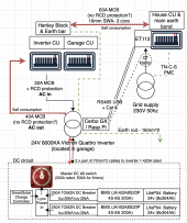
ESS self consumption.png

It appears for ESS to work in a non trivial setup then an ET112 is required "as a Grid meter and used as control input for an ESS System." This seems to reduce the need for a large rewire of the property.

Some have noted the use of an additional CT clamp to increase response time.

In the updated diagram I've marked two red lines that transmit the energy from batteries for self consumption to entire property. I've seen forums say the lines transmitting generated power shouldn't be RCD protected only fused hence the MCBs. Is this right?

An earth connection is included and extended to inverter and onwards to an earth rod.

I would've thought the AC IN is bidirectional, thereby eliminating the red line of AC OUT as in my diagram. I couldn't find this in the ESS documentation or in the model specs.

Otherwise, ideally it would just be one line from consumer unit to inverter AC IN and I'd probably set it to 40A (with RCD protection) - thoughts?
 
Last edited:
I believe Victron Quattro can't use an external CT clamp to sense the load (correct me if wrong). It can only use the ET112 device (which seems very overpriced when other modes enabled energy meters using the same standard are available for £20).

Can't find the link but apparently the suppliers earth can't be relied upon so a separate earth needs to be implemented.

Apparently the Quattro's can use 'AC In' as input and output so only one connection to the house mains is needed if using ET112.

Please correct me on anything as I'm learning.
 
Back
Top