


You are using an out of date browser. It may not display this or other websites correctly.
You should upgrade or use an alternative browser.
You should upgrade or use an alternative browser.
Best material for buss bars?
- Thread starter Dyotat100
- Start date
MisterSandals
Participation Medalist
Gold and silver are better conductors and would make the highest quality bus bars if that is what you mean by “best”.Was wondering what is really best? Plam is ro make them out of copper bar.
MisterSandals
Participation Medalist
Ah, someone with skill and fancy toys, I'm jealous!Plan on putting them in the mill and decking them so there flat.
If you want to do the math (or maybe someone else here has some spare brain cycles?) you can calculate the cross section area and compare that to AWG cross sections. With the correct AWG equivalent you can determine the maximum amperage that can be run thru your copper bars.Was thinking 5/8"×3/16"
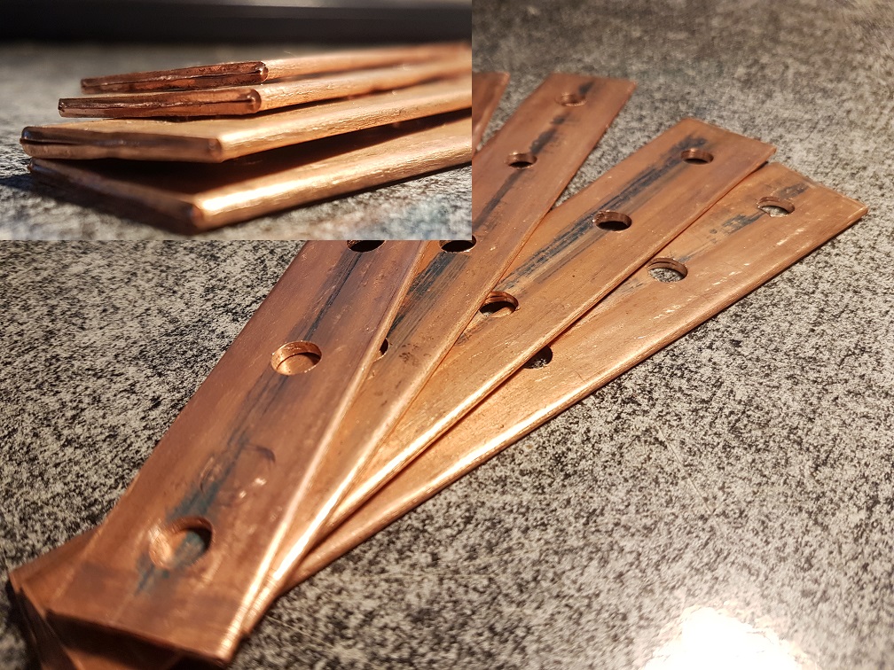
I use 5/8" copper tubing squeezed in a vise and then hammered flat. My only recommendation to you since you seem completely capably would be to make the holes slotted to allow for pack expansion and optimal placement without stress on the fairly fragile mounting points.
Yes I will make small slots in them. Copper pipe is thinner then 1/8" I would say when smashed.
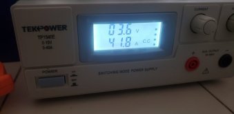
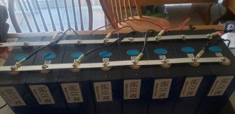
First I used one wire. Noticed the voltage was dropping off away from it. So I added another at the other end. That brought it up from 25 amps to 37.5 amps. Today I went and bought more wire and added a 3rd. Holding at 41.8 amps.
I started this at 3:30 pm on Saturday at 3.293 volts. I'm now at 3.382 volts.
Attachments
jasonhc73
Cat herder, and dog toy tosser.
3.382 is more than 99% SOC.Yes I will make small slots in them. Copper pipe is thinner then 1/8" I would say when smashed.
First I used one wire. Noticed the voltage was dropping off away from it. So I added another at the other end. That brought it up from 25 amps to 37.5 amps. Today I went and bought more wire and added a 3rd. Holding at 41.8 amps.
I started this at 3:30 pm on Saturday at 3.293 volts. I'm now at 3.382 volts.
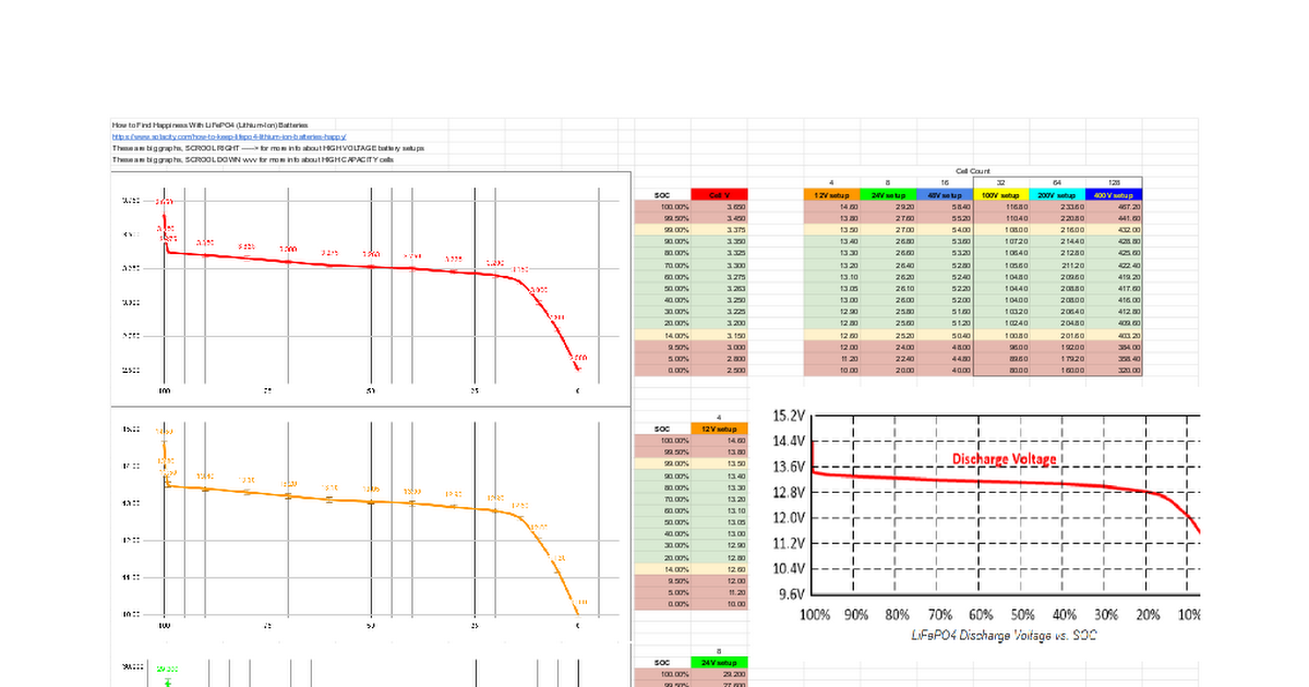
LiFePO4 Battery Voltage
Sheet5 How to Find Happiness With LiFePO4 (Lithium-Ion) Batteries <a href="https://www.solacity.com/how-to-keep-lifepo4-lithium-ion-batteries-happy/">https://www.solacity.com/how-to-keep-lifepo4-lithium-ion-batteries-happy/</a> These are big graphs, SCROOL RIGHT -----> for more info about HIGH V...
MisterSandals
Participation Medalist
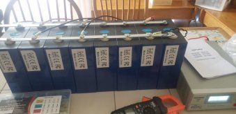
Ya lost me. From your picture, it looks like you are doing a parallel charge of some sort. The two wires on the right, on the same end of the battery are a problem. You should have + lead on one end of the group and - lead on the other. Adding the midpoint wires will help somewhat.First I used one wire. Noticed the voltage was dropping off away from it. So I added another at the other end. That brought it up from 25 amps to 37.5 amps. Today I went and bought more wire and added a 3rd. Holding at 41.8 amps.
I started this at 3:30 pm on Saturday at 3.293 volts. I'm now at 3.382 volts.
What are you trying to do?
MisterSandals
Participation Medalist
The thickness is only half of the equation. Mine are over an inch wide when "delicately hammer machined".Copper pipe is thinner then 1/8" I would say when smashed.
I'm top balancingYa lost me. From your picture, it looks like you are doing a parallel charge of some sort. The two wires on the right, on the same end of the battery are a problem. You should have + lead on one end of the group and - lead on the other. Adding the midpoint wires will help somewhat.
What are you trying to do?
MisterSandals
Participation Medalist
Thats a good thing to do.I'm top balancing
Looking at this old photo (from my show and tell thread), this looks my top balance for 8 cells.
EGADS, this was a poor picture to post. It shows that I was making the same mistake that you were: applying power to + and - on the same end of the bank. I KNOW i eventually fixed this...
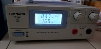
I do not have a bench charger/power supply, only a DC to DC charger (the one pictured is one of several that i tried, this model had a tendency to die after a few uses). The 4S battery on the right is charged by solar and is the charger input/source.
Eventually after reconfiguring the 8 cells to 2P4S, I top balanced the other 4 cells. I charged each parallel set up between 3.6v and 3.65v. They've been in service in my RV and greenhouse, or discharged to 3.25v in storage mode ever since.
schmism
Solar Addict
Mine were "delicately machined in the shop press"The thickness is only half of the equation. Mine are over an inch wide when "delicately hammer machined".
MisterSandals
Participation Medalist
Just one more step before you have the elegant hammered finish... :*)Mine were "delicately machined in the shop press"
MisterSandals
Participation Medalist
I suspect that all your wires are applying a fairly distributed and balanced charge.I took off all the wires and left just one. Put + on one end and - on other. Amps dropped to 24.5.
So I put back on all my wires this way and now back to 41.8 amps
I think wrong and will hurt it?
I am at a loss as to why your charging amps changed so much between the two configurations. Can you explain what the settings are (constant current? constant voltage? and what amounts)?
I do see the photo with the charger and display.
Perhaps someone who actually owns a bench top charger, especially that one can chime in and help?
FilterGuy
Solar Engineering Consultant - EG4 and Consumers
Well with in reason. I have 8 280 eve cells. Making a 2p4s pack. Plan is configure like this. Will make the sides all one piece. Plan on putting them in the mill and decking them so there flat.
Was thinking 5/8"×3/16"
Thanks
I use copper . For marine applications, tin plated copper
I like that you are making the longer bars out of one piece. Stacking short bars to create the long bar just adds a lot of connections that add resistance and create voltage drops.
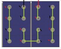
For 2P4S I like these layouts better:

For the green 'boxed' connections in the middle, you can use thinner material if you like. Also, for the boxed connections, put the 'serial' bars between positive and negative down first. (One poster commented he was going to make square 4-hole bars for the boxed connections.)
The purple bars on the ends should be heavy duty to minimize voltage drop between parallel cells.
MisterSandals
Participation Medalist
Just out of curiosity, what is it about those that you like? Is it the box areas or the battery shape/form?For 2P4S I like these layouts better:

The battery shape for me is dictated by the battery compartment in my RV. Here a a pic (not mine!) of the shape/form that I am using. The shape of your "B" is close to working for me but the wiring is pretty limited to + on one end and - on the other.

FilterGuy
Solar Engineering Consultant - EG4 and Consumers
I usually use 3/16 or 1/4 thick and 3/4 wide copper. There are places where I could use 1/8" but I figure if I am going to go through the effort of fabricating my own bars, I might as well go thicker than needed.
Note: For Fortune cells, I use 1" wide bars because of the really big holes needed for the big posts. However, the posts are short enough that you must be careful how thick the bars are... particularly if there are stacked bars.
BTW, since you have a mill, you can make the holes slightly oval to accommodate slight variances without making huge holes.
Be sure to sand off all the grime and oxide on the copper. I also like to lightly steel wool the aluminum pads on the cells before installing the bars.
FilterGuy
Solar Engineering Consultant - EG4 and Consumers
Just out of curiosity, what is it about those that you like?
The reason I like the layouts is that it minimizes voltage differences between parallel cells, With those 4-bar connections, the voltage on each of the parallel cells is going to be dang near identical. The only place there will be a voltage difference between parallel cells are the 'end' bars. That is why I say they need to be heavy duty. I also suspect that making the long 4 hole bars out of one piece of copper helps a lot.
The reason to be concerned about voltage difference between parallel cells is that it causes uneven wear on the cells.
Here is the rub: Does it make a big difference or is this a lot of work for minimal gain? I can't say. I really don't know how big of a deal this is.
Ok I went back to one wire so the power supply is now in constant voltage. + one one end and - on the other. I'm at 3.435 an d 16.5 amps. It started climbing fast so I'm watching it.
I set it at 3.64 v when I started. I took all leads off and double checked and it is still at 3.64 volts with no load.
Thanks for all the input. I have been reading a lot here.
My batteries shipped on 11-12 and showed up 1-2.
I set it at 3.64 v when I started. I took all leads off and double checked and it is still at 3.64 volts with no load.
Thanks for all the input. I have been reading a lot here.
My batteries shipped on 11-12 and showed up 1-2.
Attachments
MisterSandals
Participation Medalist
Stick a fork in it, its done.3.64 volts with no load.
When you have it disconnected and before you build up your battery, label your batteries (A, B, C, D) and make a note of what voltage they EACH settle to on their own. Make note of anything else that you observe or measure.
You'll see.
Similar threads
- Replies
- 7
- Views
- 248
- Replies
- 6
- Views
- 332
- Replies
- 33
- Views
- 1K