diy solar

diy solar

BMS deactivates the output without errors

xtesla26

New Member
Joined
Apr 13, 2023
Messages
7
Location
Italy
Hello everyone, since a few days I have mounted my PV system, unfortunately during the first tests I found a big problem, the bms disconnects the inverter after the load is on for a few minutes, looking at the values on the app (SMART BMS) just before the bms disconnection I can't find any values that can suggest me the reason for the disconnection, the temperature is okay, the battery and cell volts are in the right ranges, and the difference in volts between cells is not excessive, also the bms disconnects for a few seconds and then reattaches the inverter, which with the load connected turns off again after a few minutes and so on in a loop

the minutes before disconnection varies depending on the load,
for an 1800w load the disconnection occurs after 2 minutes, while for a 1250w load the disconnection occurs after about 40 min

I tried to figure out what the problem is but nothing, I can't find the solution, I tried to read the errors via Bluetooth from the app (SMART BMS) but it tells me there are no errors and fails to send the email

my setup:
BMS: Daly BMS ,12v, lifepo4, 30A
Equalizer: active equalizer 4s lifepo4 5A
Charge controller: POWMR MPPT 60A
Inverter: Vevor 12v Pure Wave 230v 2500W - 5000W
Batteries: 4 LifePo4 3.2v battery 280h Discharge/charge current 0.5C Max 1C REPT

IMPORTANT!!!
following a youtuber's video, I have using a small BMS used as a relay, i.e. the inverter and charge controller are connected directly to the battery interrupted though by relays controlled by the bms, i.e. the BMS sees no current in and no current out except for the negligible one from the two relays, of course there are also fuses to control overcurrents, this is done to not overheat the
BMS with large currents and to save money in buying a small BMS instead of a large one.

Has anyone had the same problem or can help me? Thanks in advance

PS: please excuse me for my English
 
If your BMS' are 30A each. If that is the case and 4 packs are set in Parallel, then collectively they can output a max of 120A.
12V X 120A = 1440W (uncorrected for efficiency losses, which in general is about 15%, depending on Inverter.
1440W÷230V=6.2A (uncorrected)

12V X 250A (recommended Max limit) = 3000W.
3000W÷230V=13A *Uncorrected.

I would strongly suggest that you get at least 100A capable BMS or better yet, would be 200A BMS which would allow for One Battery Pack to service loads if any of the others shutdown.

Hope it helps, Good Luck.
 
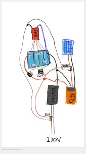
Thank you very much for your answer, let me explain better, the inverter is not connected to the P- BMS, it is connected directly to the battery, in the middle of the connection between the inverter and the battery is a relay which is driven by the BMS, that's why I can theoretically draw more than 30A, because the current does not go through the BMS
 
Yes, I understand that this is a Relay controlled BMS but you are still exceeding what it is capable of delivering and this is why it shuts down. The BMS may be OK but the Relay is underrated for the power delivery required.

A good diagram or photo's would be more helpful for anyone trying to assist you.
 
I would run the system with a smaller load on the inverter, say 100W. Look at the BMS voltage and current. Your current should be just what is needed to energize your relay. The BMS sees the voltages and my guess would be low voltage on a cell. A heavier load may pull down the weaker cell to give you a low voltage disconnect. When disconnected, the voltages float up and the BMS re-engages the relay.

What voltages are you seeing?
 
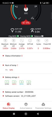
Thank you very much for your reply, I think you are right, maybe the times go down fast and are not shown on the screen, actually one cell (always the same one , the 3) always stands at the edge of the detachment, I attach the image of the simplified schematic of the system (sorry for the childish drawing), and I attach photos and videos showing one cell much lower than the others, it should not be like that, right? is it too abnormal?


WhatsApp Image 2023-04-13 at 21.29.01.jpegWhatsApp Image 2023-04-13 at 21.31.26.jpeg
 

Attachments

  • Video.zip
    11 MB · Views: 6
It looks like you might just be asking too much of this battery. Look at the voltage slump a few seconds into the video... It goes from 12.9V to 12.3V to 11.9V very quickly. I'm assuming a load gets turned on somewhere around the 5 second mark? If it's 1800W, that's over 150A at 11.9V, which is above the 0.5C rate for the cells.
I can't speak to the lack of reported errors for this particular BMS, but my guess is you're triggering either cell under voltage, or battery undervoltage. What are these set at? You get down below 2.8V on cell 3 and 11.9V on the pack. That pack voltage is very low for a nominal 12V LFP pack.

But, the bigger issue I see here is that I'm not 100% sure your setup will protect your battery from overcharging! Over discharging should be protected: If a cell or the pack get too low, the discharge MOSFETs will turn off and open the relays. All good there.
BUT! If cell or pack voltage goes high, the BMS likely only turns off the charge MOSFETs, which will do nothing to the relays: they will always be 'seen' by the BMS as a load, and so disabling charging with the BMS won't turn them off! Your cells will just keep charging until... Well, until something bad happens.
Maybe I'm missing something here, but I think this set up is dangerous. At the very least, I would do some testing to see if the BMS can act to stop charging. That test might be as simple as toggling the 'Chg MOS' switch on the BMS and see if it opens the relays. But honestly, compared to the price of those cells, a proper BMS isn't that expensive.
 
Mighty low voltage, the battery could sure use a full charge. Also, I think the inverter relay is on the wrong side. If it is on the AC side, when it opens the inverter will still pull a little from the battery.
 
It looks like you might just be asking too much of this battery. Look at the voltage slump a few seconds into the video... It goes from 12.9V to 12.3V to 11.9V very quickly. I'm assuming a load gets turned on somewhere around the 5 second mark? If it's 1800W, that's over 150A at 11.9V, which is above the 0.5C rate for the cells.
I can't speak to the lack of reported errors for this particular BMS, but my guess is you're triggering either cell under voltage, or battery undervoltage. What are these set at? You get down below 2.8V on cell 3 and 11.9V on the pack. That pack voltage is very low for a nominal 12V LFP pack.

But, the bigger issue I see here is that I'm not 100% sure your setup will protect your battery from overcharging! Over discharging should be protected: If a cell or the pack get too low, the discharge MOSFETs will turn off and open the relays. All good there.
BUT! If cell or pack voltage goes high, the BMS likely only turns off the charge MOSFETs, which will do nothing to the relays: they will always be 'seen' by the BMS as a load, and so disabling charging with the BMS won't turn them off! Your cells will just keep charging until... Well, until something bad happens.
Maybe I'm missing something here, but I think this set up is dangerous. At the very least, I would do some testing to see if the BMS can act to stop charging. That test might be as simple as toggling the 'Chg MOS' switch on the BMS and see if it opens the relays. But honestly, compared to the price of those cells, a proper BMS isn't that expensive.
Yes, the load used during the video was 1800w, but I have the same effects even with the 1250w load, and I think the parameters used during that video were, min 2.5v per cell and 11v for the whole battery and 0.250v delta between cells. i later changed the settings by putting the delta between cells to 0.4v, getting with the 1250W load also delta between cells of 0.35v, is this a normal value or my cells are defective?

to my sorrow, I think you are right, the bms controls the relay placed between the panels and the charge controller by turning off the P-, and I think that this happens only in case of low volts protection, because I think in case of high volts it doesn't disconnect the P-, I will check and update you, thank you very much
 
Mighty low voltage, the battery could sure use a full charge. Also, I think the inverter relay is on the wrong side. If it is on the AC side, when it opens the inverter will still pull a little from the battery.
You are right, but I think that small current is not a problem, I think it can only become a problem if there is a malfunction inside the inverter, surely it would be better to prevent and fix the problem
 
with the 1250W load also delta between cells of 0.35v, is this a normal value or my cells are defective?
I don't see any indication that the cells are defective there. You're pulling more than 100A, you should expect the voltage to decrease, and maybe not uniformly. It does look like the cells (especially cell 3) might be at a low state of charge. If you fully charge the battery and repeat the test and the voltage drops that quickly, then you might have a problem.
battery and 0.250v delta between cells. i later changed the settings by putting the delta between cells to 0.4v
Do you mean that the BMS cuts off with a certain differential cell voltage? I've never seen that functionality before.
 
I agree that the cells need to be charged up a bit more before you can do a real test. Start with the cells above 3.3 volts and then watch what it does. You may have a poor bus bar connection between cells. At over 100 amps, it does not take much resistance at all to cause a voltage drop. The BMS will detect that drop as a failing cell. If you have a good sensitive volt meter, load the system to about 500 watts and try to measure the voltage from the actually cell terminal to the bus bars. 0.001 ohm is a decent connection. At 500 watts, you will be pulling over 40 amps. That should produce a voltage drop of about 0.040 volts less is better, a little more might be okay, but check every terminal to every bus bar and they should all match. If you have one that reads double, you have a problem and the connection needs to be fixed. Aluminum cell terminals can easily have an oxide layer that makes a poor connection. You may need to sand the terminals to clean off the oxide and be sure to use an aluminum anti oxidation compound like "NOALOX" or "Ox-Gard" to keep it from oxidizing after it is assembled.

Also keep in mind that the reported state of charge from the BMS is completely useless in this setup. Since the load current is not going through the BMS it does not know that energy is being taken out of the cells at all. That can explain why it was showing 47.9% SoC with a cell at 2.8 volts. All of the energy in an LFP cell is really between 3.0 and 3.4 volts. The knees at the top and bottom of the charge curve are only 10% of the battery capacity.

How much charge power do you have available? You listed a 60 amp charge controller, but not the PV panel watts. I would certainly get a BMS large enough to run the charge current through the BMS. That will take care of the over charge protection issue. Then the relay can disconnect the inverter for discharge protection. That is how Will did it in his video.
I charged the battery up to 13.4 volts and still got the same results

unfortunately my voltmeter is not accurate enough, I will try to optimise the connection by disassembling and re-modelling the bus bas

I have 2 350w panels, so I can't connect the charge controller to the BMS, however I decided to buy a 250A BMS and set up the system with standard connections
 
700 watts at 12 volts would be a peak of over 58 amps, so yes, you need a bigger BMS. More realistic charge current will be more like 40 amps, but that is still more than your 30 amp BMS can take.
 
I agree that the cells need to be charged up a bit more before you can do a real test. Start with the cells above 3.3 volts and then watch what it does. You may have a poor bus bar connection between cells. At over 100 amps, it does not take much resistance at all to cause a voltage drop. The BMS will detect that drop as a failing cell. If you have a good sensitive volt meter, load the system to about 500 watts and try to measure the voltage from the actually cell terminal to the bus bars. 0.001 ohm is a decent connection. At 500 watts, you will be pulling over 40 amps. That should produce a voltage drop of about 0.040 volts less is better, a little more might be okay, but check every terminal to every bus bar and they should all match. If you have one that reads double, you have a problem and the connection needs to be fixed. Aluminum cell terminals can easily have an oxide layer that makes a poor connection. You may need to sand the terminals to clean off the oxide and be sure to use an aluminum anti oxidation compound like "NOALOX" or "Ox-Gard" to keep it from oxidizing after it is assembled.

Also keep in mind that the reported state of charge from the BMS is completely useless in this setup. Since the load current is not going through the BMS it does not know that energy is being taken out of the cells at all. That can explain why it was showing 47.9% SoC with a cell at 2.8 volts. All of the energy in an LFP cell is really between 3.0 and 3.4 volts. The knees at the top and bottom of the charge curve are only 10% of the battery capacity.

How much charge power do you have available? You listed a 60 amp charge controller, but not the PV panel watts. I would certainly get a BMS large enough to run the charge current through the BMS. That will take care of the over charge protection issue. Then the relay can disconnect the inverter for discharge protection. That is how Will did it in his video.
@GMXnow ,
Thank you very much for your help, it was of paramount importance, I checked the connections to the busbars of the various batteries and indeed some of them were slow, probably loosened during transport from one location to another, so the problem is now solved, the bms was disconnecting because of the difference in volts between the cells, the problem of not being able to read the error log from the app remains, but I'm glad I've solved my problem, and I've already bought a 250A BMS to return to the normal system configuration.

Thank you all very much for your help
 
Back
Top