diy solar

diy solar

BMS for 48V bank of EVE 280AH Cells?

> I used to use Class T fuses, that is till one day, one literally disintegrated in my hands! A "Littlefuse" brand no less. [Steve_S]

You were disappointed there was no explosion? Maybe it simply did its job properly without any theatrics? What were your hands doing inside live circuitry? Enquiring minds run omok.
--
 
3. Chargery designed separate Charge and Discharge leads for those who have systems that have separate charge and load buses which gives you the most flexibility. In that case, a low voltage condition BMS trip would not trip your charger for example, but would drop your load bus only. For a high voltage case, the BMS can keep the load on and drop the charger bus. However if you have a combination inverter/charger like I do (Victron Multiplus), I can't use that level of flexibility because the load and charger bus is the same on the Multiplus. What I can do is set the charger and inverters parameters to react to voltage and temperatures and act accordingly, but I use the BMS to disconnect the battery as a last resort if any high/low condition happens outside of the parameters that I set on my loads and chargers. As I indicated in my diagram above, you can wire the Chargery through small low power SSRs that are series connected with the coil on your main relay and get away with one more expensive main relay. The low power SSRs are cheap - like $12 cheap.

@bdbugbee Hello, Bdbugbee, I plan to add Victron Multiplus 2 for increasing my actual self consuption rate (on-grid installation as explained on the attached illustration) and I'm looking for how to stop charge/discharge in case of overvoltage/undervoltage detected by the BMS.
If I understand well your explanation, you are not using the 2 internal Multiplus 2 relays (Aux I/O & Temp Sensor) to inform the inverter/charger to stop load/charge in case of overvoltage/undervoltage of the battery pack, correct?
So how do you parameter the Multiplus to stop load/charge in this conditions?
Maybe a Victron BMV 702 (or 712) can inform the Multiplus by VE Bus, but not sure.
Additional question, which BMS (brand & model) are you using for your batery pack?
Thanks for your answer.
 

Attachments

  • Untitled Diagram-3600W - Micro onduleur - Battery - Multiplus 2 (1).jpg
    Untitled Diagram-3600W - Micro onduleur - Battery - Multiplus 2 (1).jpg
    51.1 KB · Views: 38
@bdbugbee Hello, Bdbugbee, I plan to add Victron Multiplus 2 for increasing my actual self consuption rate (on-grid installation as explained on the attached illustration) and I'm looking for how to stop charge/discharge in case of overvoltage/undervoltage detected by the BMS.
If I understand well your explanation, you are not using the 2 internal Multiplus 2 relays (Aux I/O & Temp Sensor) to inform the inverter/charger to stop load/charge in case of overvoltage/undervoltage of the battery pack, correct?
So how do you parameter the Multiplus to stop load/charge in this conditions?
Maybe a Victron BMV 702 (or 712) can inform the Multiplus by VE Bus, but not sure.
Additional question, which BMS (brand & model) are you using for your batery pack?
Thanks for your answer.
I have an 8S LiFePo4 280 AH battery bank. I do use the Multiplus Aux and Temp Sensor relays to control the Inverter and Charger functions on the Multiplus as a first line of defense in case of a low or high voltage situation. I also have a 24/12 V converter to feed my 12 volt loads which is controlled with a BMV 712 low voltage relay. I also use my BMS (Chargery BMS8T) hooked to two SSRs whose outputs are connected in series across my 24V bus to power the coil on a main cutoff relay as a last line of defense if the Multiplus fails to turn off in a high/low voltage situation or the converter fails to cut off in a low voltage situation. I have my Multiplus charger set to 27.6 v for absorption with 27.0 volts float and the inverter set to cut off at 23.0 volts. I have the converter set to cut off at a bank voltage of 24 volts. My BMS is set to cut off the main relay on the battery at >3.6 volts or <2.8 volts on any individual cell.
 
Thanks @bdbugbee for the explanations, I understand alomst all except this one : " I do use the Multiplus Aux and Temp Sensor relays to control the Inverter and Charger functions on the Multiplus as a first line of defense in case of a low or high voltage situation "
-> what do you plug on the Victron Aux and Temp Sensor relays?
Actually, I mis-spoke about the Aux and Temp Sensor being the first line of defense. They are actually a redundant last line of defense because I feed the Aux and Temp Sensor relays on the Multiplus from the Chargery BMS outputs so they shut off the Multiplus if the BMS trips in addition to the BMS cutting off the main relay to the battery bank. The first line of defense are the invertor and charger voltage cutoff settings on the Multiplus. Sorry for the confusion.
 
Actually, I mis-spoke about the Aux and Temp Sensor being the first line of defense. They are actually a redundant last line of defense because I feed the Aux and Temp Sensor relays on the Multiplus from the Chargery BMS outputs so they shut off the Multiplus if the BMS trips in addition to the BMS cutting off the main relay to the battery bank. The first line of defense are the invertor and charger voltage cutoff settings on the Multiplus. Sorry for the confusion.

Hello @bdbugbee , OK understand (I thiink). Chargery BMS have 2 relay outputs : "Charge controller" + "Discharge controller"
-> you plug this 2 outputs to the AUX + Temp sensor Multiplus 2 I/O
and also
-> you use the Chargery BMS outputs to disconnect charge/load in case of undervoltage / overvoltage as illustrated in the below picure

Capture.JPG
 
The battery layout in this diagram above is crap. There are better was to do it....Just a FYI, I wouldn't want someone to follow it. You shouldn't need diagonal bus bars.

The rest of the layout appears fine.
 
Hello @bdbugbee , OK understand (I thiink). Chargery BMS have 2 relay outputs : "Charge controller" + "Discharge controller"
-> you plug this 2 outputs to the AUX + Temp sensor Multiplus 2 I/O
and also
-> you use the Chargery BMS outputs to disconnect charge/load in case of undervoltage / overvoltage as illustrated in the below picure

View attachment 24053
Your description is generally a correct interpretation of how I have my system set up, but the diagram is not. Since I don't have a separate Load and Charge bus, I use one main battery cutoff relay whose coil is fed by two SSRs in series with my 24V bus as shown in the attached diagram. The SSRs are fed by the BMS Charge and Discharge controllers. I did this because I didn't want to connect the BMS outputs across a 24V bus to directly feed the coil, and to minimize the current draw on the Chargery BMS outputs to keep the coil energized (note my diagram does not show the wiring to the Multiplus, just the main battery cutoff relay).
IMG_3300.jpg
 
great resource here, am a newbie fixing to build a simple 48v 560ah bank.guess i have tons of reading to do, as my plan was to have 2 parallel banks of 48v 280ah with separate bms....end of story:)
 
Just ordered 32 of the EVE 280AH cells for my first DIY LiFePO4 build for an off grid solar system using two MPP Solar 3KW inverters (paralleled) and 5KW PV array.

First question; which is better, a) two banks of 16 cells, each with a seperate BMS, then connected in parallel (16S,2P); or b) parallel the cells first and then connect in series (2P,16S) with a single BMS?

Second question; any recommendations as to which BMS I should consider getting for my application using the EVE 280AH cells , 16S?
Here are my thoughts so far with a similar situation.

I was just looking at overkill solar BMSs becuase of the warranty, a possibility of a BMS going bad faster than anything else, service, not far from me, he does 8g wires, and Will mentioned they were his favorite bc the chargery relays reach 130 deg+ etc. The biggest BMS he sells are 8s, so 4 batteries of 8 sells. I guess it would be easier to move 4 batteries around vs 2 larger ones, but I need to read that victron battery bank design link. Also maybe it would be easier to service the packs with a new cell if one goes bad if they are smaller. But 4 BMSs is a lot more than just one electrodacas or chargery, although its really hard to find comparisons about all the different ones.

I want more future proof if I add a mother in law cabin and 100a max seems low. However, I'm wondering if my math is right in my head. 100a max discharge from the battery is only 2400w at 24v/8s. I was looking at getting two up to four 3000w or three 4000w MPPs stacked. The first two stacked encase my wife wants to use the microwave, AC, hair dryer, coffee pot all at once and doesn't think about it a burns up another hair dryer or something worse. Plus a dual stacked system gives me a spare fairly unused one. Its making me think I could only get two 4000watt inverters to stay under a 9600w max for the whole 48v system (2400w x 4 batteries) with 1600w until I hit the max. Or three 3k inverters=9000 watts with 600w until I hit the max. At 9k it seems like the BMS would get hot maxed out, if I had a friend visit my cabin with his RV or we built a mother inlaw and we had a 3k inverter to run theRV/ mother inlaw while we had up to 6k for the cabin. Its not great future proofing vs 6k each. So a third or fourth stacked 3k in the future wouldn't be the way to go. I guess I could always add more panels and batteries, but I'm going for a 28kwh battery system. It should run 2 cabins, the limit becomes when people who aren't used to off grid use the 110v washer/dryer combo 1500w, + microwave 1200w, make toast 1000w, dry hair 1500w =5200w etc all at once. For $700 more a second All in one mpp would be great for both cabins.

Does the amp rating get averaged over the 4 BMSs?
 
Last edited:
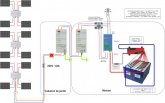
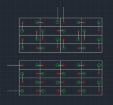
I'll chime in as well and strongly suggest two 16S/48V packs in parallel, each with a 16S BMS to manage/monitor all the cells. The redundancy is a key factor, especially if one "Pack" in the battery bank decided to misbehave for some reason. Paralleling Packs is not difficult but can cause problems if not done properly, to that end, Victron wrote up a great guide on wiring your battery packs & banks up properly, here is the link: https://www.victronenergy.com/upload/documents/Wiring-Unlimited-EN.pdf

The Chargery BMS uses two relay/contactors, one for charge control, the other for discharge control. In a Common-Port Configuration which shares the same DC LLines for both Charge/Discharge an opti-coupler can be used which accepts both relay signal but only actuates a single relay. This is heavily discussed in the Chargery BMS Thread (see my signature). There is also a page of information related to such in the New Chargery 4.1 Owner's Manual (not available yet). The Amperage handled by a BMS which uses relays can easily exceed those with FETS because the relays/contactors are available from 100A to 1000A DC and so they bear the load, not the actual BMS electronics.

Other "Smart BMS" may be an option as well. I should point out that MOSFET Based BMS' are pretty common and are used by many folks with great success. They do have limitations in so far as Amperage Handling because over 200A things have to become quite monstrous and heat dissipation is an issue, especially for the lower cost ones. With these also you ave to have a certain amount of buffer, for example, if you have 200A continuous you would want at minimum a 250A capable BMS so you stay below the maximum threshold of 250A.

Another BMS worthy of serious consideration is the TinyBMS, LIink Here: https://www.energusps.com/shop/product/tiny-bms-s516-150a-750a-36?category=4 which is a very capable & solid BMS that also is very flexible & configurable, depending on your use case, needs and wants. NOTE the prices there are shown in € Euros

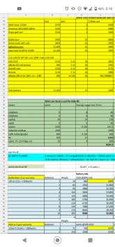
A consideration prior to buying more gear. 280AH EVE Cell pack can accept a heavy charge as well as discharge @ 1C which is 280A. It does take a significant amount of juice to charge these babies! The deeper the discharge the longer it takes to charge them up. Quite often people forget to calculate their solar charging capacity based on the LOWEST SUN HOUR DAYS which depends on your locality. This Solar Angle Calculator is lightweight but VERY handy, just select your location details from the dropdown lists and it will give you the basics without much fussing around. LINK HERE: http://www.solarelectricityhandbook.com/solar-angle-calculator.html

Hope it helps, Good Luck.
Steve
Could you explain the basic pros and cons of the different BMSs if its easy for you please. Any comparison would be great
 
Last edited:
Could a circuit breaker with remote trip (shunt trip) capability be used instead of mechanical relay with a BMS? I was planning on having a circuit breaker for a) battery disconnect b)short fault protection ; so could a remote trip circuit breaker provide the third function of disconnecting the battery controlled by BMS? Sort of an all in one battery disconnect for an all in one solar system :unsure:?
Good question, a circuit breaker makes sense to me
 
Could you explain the basic pros and cons of the different BMSs if its easy for you please. Any comparison would be great
That would require a BOOK.

Not all Relays/Contactors are the same. Some use more power & as a result they generate heat. Energy Savers like the TE/Kilovacs, Gigavac's & Dongya DHV's use very little power and don't make heat, and then we have SSR's (Solid State Relays) which sip power & no heat generated either.

Simplest way to put it. Typically FET Based BMS' cap at 300A but you never want to reach their maximum capacity as that is dodgy at best. BMS' with relays are independent of the amps/volts of the battery packs as the Relay/Contractors are bought according to the specs required. So if you need 200A or 500A then you buy relays accordingly. FET Based is simpler (less pieces) where Relay based has more bits to deal with. If Smart or Not depends on model both FET & Relay models can have "smarts". Pricing is everywhere, all depends on make, model & features/functions.

So if I need 16000watts. two stacked 4k inverters only ine mostly used for the house, and two more for mother inlaw and shop/RV pad in a year or two.

The only way I see getting enough amps (16000w) from enough BMSs is to do the relays if for example a fet BMS max amps is 100a. Those 250a china BMSs with 10g wire are not real 250a, no way.

For example with a good Overkill BMS using 32cells 16s2P = 48v with two Overkill 16s 100a BMSs is only 200amps. = 24v x100a = 2400w x 2 =4800w? Or is that 48v at 100a x 2= 9600w? I think its 4800w max.
 
This is where things get complicated.
1-4 Battery packs in a bank can be managed with assorted BMS' and it's generally "okay".

Above 4 packs and things get weird. If you have GOOD Tier-! grade Inverters that can use CanBus to interact with the BMS' then you are better to look at Decentralised BMS' systems which have a slave BM<S on each pack connected to the Master BMS that communicates with the Inverter Susbsystem, to allow charge or discharge or not, many will also throttle and control charge based on programming.

The simpler FET Based units are not capable of such, neither are Chargery and many others... It is a different level of equipment. Remember, these are the Battery Pack "Guard Dogs" nothing more or less and that is a factor.

There are High Output 5000W up to 15,000W AIO Systems which provide either 240V Split Phase @ 60hz for North America or 220V/50Hz for Europe & elsewhere. These "Big Boys" can run with 48V and some even up to 72VDC or 96VDC (much less common and NOT DIY suitable really unless you are an electrician and trained... beyond 48V get's into nasty territory is you mess up... Remember high end Welding is done with DC Power !

I understand you are trying to wrap your head around all of this.. it is a lot to absorb and get a handle on. Once you get a better handle on what you want to setup and once you've looked at your budget and figured out what is reasonable and doable then we can get into Minutia and fine details... First & most important thing is to get real numbers for power usage & demands...

240V X 200A = 48,000W. Your service panels are the maximum your home can pull... It is most unlikely that you exceed what service you have.
Yeah I I calculated everything already.

I need 18000w max in 24 hrs.

10kw of panels 250w 30v

32cells at 280ah 48v = 28000kwh

48v system - was going to do 2 48v 3k MPP all-in-ones now and then 2 later.

Now just need BMS
 
OK, we have to come back to your calculations, you Just changed the picture big time.
The Math is essential, it changes the entire picture from top to bottom, hence why we are hung up on doing proper estimates and calculations. It can mean thousands of dollars difference in cost and how things get implemented.

So now, you say you need 18 kWh per day, that is not the same as using 18kw at one time ! Hugely different !

The Inverter is sized for the Max LOADS being drawn at any given point in time during the day, not for the Total amount of watts used within 24 hours.
A 10,000W Inverter is much more costly than a 5000W Inverter.
IF drawing 18,000W @ 48V that is 333A. If drawing 6000W it's 125A
A BMS needs to be sized accordingly. A BMS system that handles 300A is more costly, regardless if FET or Relay based controls. Higher Amps = higher cost relays and BOS (Balance of System, like Batt Wires, that can be hundreds of dollars difference, not to mention fuses, breakers etc)
It is very important to know what the maximum load potential is that can be expected to be drawn from the batteries. Now you can toss Caution to the Wind and go larger BMS system like 300A or 400A handling capability and not worry about it but it's $$$.

If using 18kWh of power per day, you x 3 days autonomy = 54kWh.
2x280AH = 560AH X 48V = 26.8kWh storage. * 280AH battery -10% for margin = 252AHx2 = 504AHx48V =24.29kWh.

So back to BMS, Depending on Inverter System (your leaning towards MPP, which has numerous models) and if it can interact with a BMS or not affects the choices & options. Unless you want to run Dumb BMS' which do not interact with each other or the Inverter & Solar subsystems. Each 48V Battery Pack will require a 16S BMS, how many Amps depends on your Loading Calc's which we do not have at this time.

Remember that batteries can cutoff, Solar Controllers don't like having any connected batteries if they all disconnect due to being fully charged. Having an inverter switch to "rest mode" when Low Volt Disconnect occurs is better than dropping it cold because then it would not be able to recharge the batteries if the sun comes up or Genset/grid power kicks in. In "Rest Mode" it can wake and do its job, dropped cold and off it will do nothing till you physically intervene. If the BMS sub-system can tell the inverter they are Low Volt some can be programmed to go into rest mode if an alternate power source is unavailable, or if available to switch to it and charge the batteries.

Have you seen HighTechLabs video's & setup ?
I feel he is building something more in line with what you're headed towards. He just did a video on SolArk AIO, they are a Tier-1 product.

I am not comfortable suggesting any BMS at this time because the information is not sorted yet. It is a very important component that is ultimately responsible for guarding thousands of dollars worth of cells, so not to be taken lightly eh.
 
Y
Yeah I I calculated everything already.

I need 18000w max in 24 hrs.

10kw of panels 250w 30v

32cells at 280ah 48v = 28000kwh

48v system - was going to do 2 48v 3k MPP all-in-ones now and then 2 later.

Now just need BMS
You seems to mix kW and kWh.
"I need 18kW max in 24h"...means nothing, or perhaps it's a typo.
If you meant 18kWh per 24H then your 10kW of panels seems pretty weak.(or perhaps I missed something).
 
Just ordered 32 of the EVE 280AH cells for my first DIY LiFePO4 build for an off grid solar system using two MPP Solar 3KW inverters (paralleled) and 5KW PV array.

First question; which is better, a) two banks of 16 cells, each with a seperate BMS, then connected in parallel (16S,2P); or b) parallel the cells first and then connect in series (2P,16S) with a single BMS?

Second question; any recommendations as to which BMS I should consider getting for my application using the EVE 280AH cells , 16S?
Hi, I’m just about to order some 280ah cells. Can I ask you what company you ordered from and how much you paid. I don’t want to make a $4000 mistake. Really appreciate any info from anyone on a good source for these cells.
 
Hi, I’m just about to order some 280ah cells. Can I ask you what company you ordered from and how much you paid. I don’t want to make a $4000 mistake. Really appreciate any info from anyone on a good source for these cells.
My bad thought this was the Basen battery thread and you were looking for the links to the cells.

I think the link is in the op
 
Last edited:
Y

You seems to mix kW and kWh.
"I need 18kW max in 24h"...means nothing, or perhaps it's a typo.
If you meant 18kWh per 24H then your 10kW of panels seems pretty weak.(or perhaps I missed something).

Original question
The 18000w in 24hrs didn't really matter, my bad for not writing things correctly. I asked a very specific question on how to calculate BMS output to an inverter. I recieved vague answers from Steve_S, and he said, " first & most important thing is to get real numbers for power usage & demands." I followed what websites said to do and came up with 18kwh. I guess technically its 18kwh for 2 days not 24hrs.

The original question but changed the grammar:
The only way I see getting enough amps to 16000w worth of inverters without spending 1000s on a Batrium is to do a BMS with relays. Is this correct? I just don't understand, for example a fet BMS max amps is 100a, so how is it possible? Those 250a china BMSs with 10g wire are not real 250a output. So how do you do 32 cells with Overkill BMSs? Buy 4 of them and put them in series?

For example with a good Overkill BMS using 32cells with his 8s 48v. 32 cells = 4 BMSs at 100a each is only 400amps. Does that equal 24v x 100a x 4 BMSs = 9600w? So thats only 9600w running all at once max from a 28kwh battery?

So, also in the end if you look at my original post I wrote he made 16s. I was wrong Overkill's BMSs are 8s 100a. I'm just trying to figure our how to feed 32 cells into max 16000w worth of inverters (eventually Four 4k inverters). In 16s 48v config x 2p batteries = 333a for 16kw or 166a per BMS. So I need legit 16s 200a BMSs

If I'm not making sense let me know.

My system calculations I did months ago after reading websites on how to size it.

I can't look at a bill to see my usage. We sold our house and live on our new land with an RV using a generator while we build. I took all the items we use and calculated the time I use them for (down to 1/8th of an hr minimum to round up) to figure out how many watts I use in 24hrs. I remember calculating 18kwh was my goal anything over would be bonus. I planned to have generator auto start also as a backup to solar and to protect the batteries if I sized too small. MPP had everything I needed and simplified things with all-in-one to get the property up and running cheaply for our RV while I built things. Then as I added more structures I could move the all-in-ones to the shop and mother inlaw.

How I got 18kwh
For example mini AC with low voltage start 500w x 12 hr = 6000wh of battery needed. I did this for everything. Microwave 1000w x 15 minutes (.25hrs), toaster 1000w 1/4 hr, kureg 1000w at .125 hrs, and so on. The excel sheet (see the green section) auto summed everything. The most I could come up with was like 9kwh so I doubled it to 18,000wh of battery needed for 2 days, we live in a desert.

The 10kw panel array size was based on what I can buy currently and will add more over time, esp when I get a shop and mother inlaw built. Its better than running on a generator like we have been doing for the past 9 months. I also don't think we will be using that much during the day so 10 kw should charge the battery quite a bit.

MPP all-in-ones
The inverters were based on affordability and adding up everything my wife might turn on at once accidentally (5000w) and to make her life happy/easy. So if I had two 3k or 4k inverters then I would still have 1k to 3k of safety margin. If she didn't over tax the system and kept things under 3k, then I might be left with a slave inverter with less wear and tear as a type of back up if the master went bad. Then when I finish the garage and add a cabin for family those two MPP all-in-ones can feed those structures and the house can get an upgrade.

How do you get 32 cells to feed 16000w

So I got 32 cells for two 16s 48v batteries bc the price was good and we thought why not buy it all now at a good price vs only having 14kwh. Its about 66% cheaper that 100ah cells. Then I got stuck trying to find 16s BMS that could handle that draw and not melt down. 10g wire on a lot of the daly/chinese 16s 200a BMSs just didn't seem good enough. I read about overkill and his upgrades to the wiring. But it was 8s 100a max. People say not to parallel BMSs and at 8s that would be 8s2p cells x 2p batteries.So I am trying to find a bms that will work. It sounds like Chargery is the way to go for such a big system without spending $800+ each on a batrium.
 

Attachments

  • Screenshot_20201203-021849.png
    Screenshot_20201203-021849.png
    308 KB · Views: 5
Last edited:

diy solar

diy solar
Back
Top