That's correct. My 280 ah cells have an internal resistance of 0.13 milliohms per cell. If you have 16 similar cells in series at .13 milliohms each, that would be about .002 ohms for the 16 cell bank. 48v/0.002 ohms = 24,000 amps at the battery terminals if you have perfect "no resistance" bus bar contact with the cell terminals. In reality every contact has some resistance so an estimate of .003 ohms for the bank is probably reasonable. That would reduce max fault current to about 16,000 amps. The point is, it is very easy to generate more than 6000 amps of fault current near the battery terminals with 280 ah cells and your main fault interrupting device needs to be rated to handle it. Also, the normal load rating of the device should be about 25% higher than your expected max normal load or charging current. If you plan to have a max load of 200 amps, a 250 amp fuse with an interrupting capability of 20,000 amps would be sufficient to protect your bank. NOTE: if you parallel the 48 v banks, each bank should have its own Class T fuse. A paralleled battery bank would double the fault current available at the battery terminals because your internal resistance is cut in half. A 48v, 560 ah battery could easily generate over 32,000 amps for a close in fault, if you assume a 0.0015 ohm bank resistance. Don't skimp on your main battery bank protection.Class T fuse at battery terminal sounds like good advice.
In the interest of learning am I correct to push 14,000A at 48V would require a total circuit resistance of under .00343 ohms? This would need to include the internal resistance of 16 cells in series, busbars, connections, cables and the wrench, screwdriver or whatever causing the short.


You are using an out of date browser. It may not display this or other websites correctly.
You should upgrade or use an alternative browser.
You should upgrade or use an alternative browser.
BMS for 48V bank of EVE 280AH Cells?
- Thread starter apctjb
- Start date
Class T fuse at battery terminal sounds like good advice.
In the interest of learning am I correct to push 14,000A at 48V would require a total circuit resistance of under .00343 ohms? This would need to include the internal resistance of 16 cells in series, busbars, connections, cables and the wrench, screwdriver or whatever causing the short.
Yes, but I used 58 V as it's the worst case (16s fully charged) you can expect so the allowed resistance would be a bit higher. And I used the datasheet max internal resistance figure because I don't have the real figure yet (and it'll be even lower so higher current).
I'll repeat it again for all members reading because it's important: Li batteries are very energy dense things with very low internal resistance, far more than lead batteries we're used to (and who can already vaporise wrenches in a fraction of a second...), do not cheap out on the protections, even more so with the bigger cells and/or higher voltages.
A fuse has two basic current ratings; Normal and Interrupting current. The normal current rating of a fuse is based on your maximum expected load/charge current under normal conditions. Using a value of 25% over your max normal load current is a good rule of thumb (for example, use a 250 amp fuse for a 200 a normal max load). The Interrupting current rating is different. That rating is the maximum current level the fuse can safely interrupt under fault conditions. Available fault current is a function of the voltage of your battery bank, its internal resistance and the resistance of your components and connections up to the point of the fault. Your fuse should be able to interrupt the worst case fault current it might see. Class T fuses with an interrupting current of 20,000 amps should be used to protect 280 ah batteries because of their very low internal resistance.Hmmm I think I am even less of an expert than you @apctjb .... Maybe there is a major point that I am missing but if I were to incorporate a fuse into my system, just all breakers now, I would think I would want a fuse that is just above the upper limits of my charge or discharge specs (which ever one is higher) no?
So for my "48v" system if my charge rate maxes out at 150 amp (based on open circuit) and my discharge is at 200amps (based on lowest system battery bank voltage and max inverter watts draw). Wouldn't I want a fuse just above the higher of the two, 200amps? So a 250amp fuse then..?
Edit: I think I get it now the "rated to interrupt a minimum" value is the max value that the fuse will work at the stated rating.?.?
apctjb
Solar Enthusiast
- Joined
- Jun 16, 2020
- Messages
- 480
My 280 ah cells have an internal resistance of 0.13 milliohms per cell. If you have 16 similar cells in series at .13 milliohms each, that would be about .002 ohms for the 16 cell bank. 48v/0.002 ohms = 24,000 amps at the battery terminals if you have perfect "no resistance" bus bar contact with the cell terminals. In reality every contact has some resistance so an estimate of .003 ohms for the bank is probably reasonable. That would reduce max fault current to about 16,000 amps
I appreciate the education and sage advice. Point taken.
Steve_S
Offgrid Cabineer, N.E. Ontario, Canada
Just to chime in here. I used to use Class T fuses, that is till one day, one literally disintegrated in my hands! A "Littlefuse" brand no less. I have since switched to MRBF fuses and never had any issues. They aren't expensive, nice & compact, easy to replace.
I use the Blue Sea ones which are the same as Samlex uses (My Inverter/Charger is Samlex).
REF: https://www.bluesea.com/products/5191/MRBF_Terminal_Fuse_Block_-_30_to_300A
I use the Blue Sea ones which are the same as Samlex uses (My Inverter/Charger is Samlex).
REF: https://www.bluesea.com/products/5191/MRBF_Terminal_Fuse_Block_-_30_to_300A
apctjb
Solar Enthusiast
- Joined
- Jun 16, 2020
- Messages
- 480
Just to chime in here. I used to use Class T fuses, that is till one day, one literally disintegrated in my hands! A "Littlefuse" brand no less. I have since switched to MRBF fuses and never had any issues. They aren't expensive, nice & compact, easy to replace.
I use the Blue Sea ones which are the same as Samlex uses (My Inverter/Charger is Samlex).
REF: https://www.bluesea.com/products/5191/MRBF_Terminal_Fuse_Block_-_30_to_300A
These look very nice, thank you for forwarding.
I checked the specifications and it appears that these fuses have a 2000 AIC at 58V, far less than the >16,000A that others suggest is necessary to protect a 48V bank using 280ah LiFePO4 cells. But clearly these are intended to provide close in fault protection for batteries.
I understand the importance of having adequately sized circuit protection devices (fuses, circuit breakers, etc.) but somewhat confused regarding the necessary AIC rating.

A fuse has two basic current ratings; Normal and Interrupting current. The normal current rating of a fuse is based on your maximum expected load/charge current under normal conditions. Using a value of 25% over your max normal load current is a good rule of thumb (for example, use a 250 amp fuse for a 200 a normal max load). The Interrupting current rating is different. That rating is the maximum current level the fuse can safely interrupt under fault conditions. Available fault current is a function of the voltage of your battery bank, its internal resistance and the resistance of your components and connections up to the point of the fault. Your fuse should be able to interrupt the worst case fault current it might see. Class T fuses with an interrupting current of 20,000 amps should be used to protect 280 ah batteries because of their very low internal resistance.
@bdbugbee Thanks for the detailed info.
These look very nice, thank you for forwarding.
I checked the specifications and it appears that these fuses have a 2000 AIC at 58V, far less than the >16,000A that others suggest is necessary to protect a 48V bank using 280ah LiFePO4 cells. But clearly these are intended to provide close in fault protection for batteries.
I understand the importance of having adequately sized circuit protection devices (fuses, circuit breakers, etc.) but somewhat confused regarding the necessary AIC rating.
View attachment 16561
Here is a link to the Class-T fuse I used. I originally considered the MRBF fuses, but I felt the interrupting rating was too low for my battery bank. This one is rated for 20,000 amps of interrupting capability.
Class T Fuse - 250 Amp - Blue Sea Systems
Use with Class T Fuse Blocks for circuit protection of devices including inverters. high interrupt capacity for large battery banks including Lithium-ion and TPPL batteries.
 www.bluesea.com
Here is the link for the fuse holder that I used with it:
Class T Fuse Block with Insulating Cover - 225 to 400A - Blue Sea Systems
Allows use of Class T fuses for high speed circuit protection of electronic equipment and inverters.
www.bluesea.com
The Class T fuses will interrupt more than their AIC rating. However they may fail spectacularly, with fragments of ceramic being ejected, and possibly a small amount of arcing. Assuming the fuse is placed in an area where this isn't a problem, I suggest they may work. For high voltage/current interruption in a commercial install a specialty breaker with arc extinguishing tech may be needed which is $$$$$$$.
mapguy525
Solar Enthusiast
Here is a link to the Class-T fuse I used. I originally considered the MRBF fuses, but I felt the interrupting rating was too low for my battery bank. This one is rated for 20,000 amps of interrupting capability.
Class T Fuse - 250 Amp - Blue Sea Systems
Use with Class T Fuse Blocks for circuit protection of devices including inverters. high interrupt capacity for large battery banks including Lithium-ion and TPPL batteries.
Here is the link for the fuse holder that I used with it:
Class T Fuse Block with Insulating Cover - 225 to 400A - Blue Sea Systems
Allows use of Class T fuses for high speed circuit protection of electronic equipment and inverters.
It seems the VTE Class T holders are a bargain compared to the Bluesea's unit linked.
https://www.vtewarehouse.com/content/electromech/fuse/html/classt/classt.php
VincentRapide
New Member
- Joined
- Jun 23, 2020
- Messages
- 30
> I used to use Class T fuses, that is till one day, one literally disintegrated in my hands! A "Littlefuse" brand no less. [Steve_S]
You were disappointed there was no explosion? Maybe it simply did its job properly without any theatrics? What were your hands doing inside live circuitry? Enquiring minds run omok.
--
You were disappointed there was no explosion? Maybe it simply did its job properly without any theatrics? What were your hands doing inside live circuitry? Enquiring minds run omok.
--
duclos_laurent
New Member
- Joined
- Jul 24, 2020
- Messages
- 23
3. Chargery designed separate Charge and Discharge leads for those who have systems that have separate charge and load buses which gives you the most flexibility. In that case, a low voltage condition BMS trip would not trip your charger for example, but would drop your load bus only. For a high voltage case, the BMS can keep the load on and drop the charger bus. However if you have a combination inverter/charger like I do (Victron Multiplus), I can't use that level of flexibility because the load and charger bus is the same on the Multiplus. What I can do is set the charger and inverters parameters to react to voltage and temperatures and act accordingly, but I use the BMS to disconnect the battery as a last resort if any high/low condition happens outside of the parameters that I set on my loads and chargers. As I indicated in my diagram above, you can wire the Chargery through small low power SSRs that are series connected with the coil on your main relay and get away with one more expensive main relay. The low power SSRs are cheap - like $12 cheap.
@bdbugbee Hello, Bdbugbee, I plan to add Victron Multiplus 2 for increasing my actual self consuption rate (on-grid installation as explained on the attached illustration) and I'm looking for how to stop charge/discharge in case of overvoltage/undervoltage detected by the BMS.
If I understand well your explanation, you are not using the 2 internal Multiplus 2 relays (Aux I/O & Temp Sensor) to inform the inverter/charger to stop load/charge in case of overvoltage/undervoltage of the battery pack, correct?
So how do you parameter the Multiplus to stop load/charge in this conditions?
Maybe a Victron BMV 702 (or 712) can inform the Multiplus by VE Bus, but not sure.
Additional question, which BMS (brand & model) are you using for your batery pack?
Thanks for your answer.
Attachments
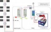
I have an 8S LiFePo4 280 AH battery bank. I do use the Multiplus Aux and Temp Sensor relays to control the Inverter and Charger functions on the Multiplus as a first line of defense in case of a low or high voltage situation. I also have a 24/12 V converter to feed my 12 volt loads which is controlled with a BMV 712 low voltage relay. I also use my BMS (Chargery BMS8T) hooked to two SSRs whose outputs are connected in series across my 24V bus to power the coil on a main cutoff relay as a last line of defense if the Multiplus fails to turn off in a high/low voltage situation or the converter fails to cut off in a low voltage situation. I have my Multiplus charger set to 27.6 v for absorption with 27.0 volts float and the inverter set to cut off at 23.0 volts. I have the converter set to cut off at a bank voltage of 24 volts. My BMS is set to cut off the main relay on the battery at >3.6 volts or <2.8 volts on any individual cell.@bdbugbee Hello, Bdbugbee, I plan to add Victron Multiplus 2 for increasing my actual self consuption rate (on-grid installation as explained on the attached illustration) and I'm looking for how to stop charge/discharge in case of overvoltage/undervoltage detected by the BMS.
If I understand well your explanation, you are not using the 2 internal Multiplus 2 relays (Aux I/O & Temp Sensor) to inform the inverter/charger to stop load/charge in case of overvoltage/undervoltage of the battery pack, correct?
So how do you parameter the Multiplus to stop load/charge in this conditions?
Maybe a Victron BMV 702 (or 712) can inform the Multiplus by VE Bus, but not sure.
Additional question, which BMS (brand & model) are you using for your batery pack?
Thanks for your answer.
duclos_laurent
New Member
- Joined
- Jul 24, 2020
- Messages
- 23
Thanks @bdbugbee for the explanations, I understand alomst all except this one : " I do use the Multiplus Aux and Temp Sensor relays to control the Inverter and Charger functions on the Multiplus as a first line of defense in case of a low or high voltage situation "
-> what do you plug on the Victron Aux and Temp Sensor relays?
-> what do you plug on the Victron Aux and Temp Sensor relays?
Actually, I mis-spoke about the Aux and Temp Sensor being the first line of defense. They are actually a redundant last line of defense because I feed the Aux and Temp Sensor relays on the Multiplus from the Chargery BMS outputs so they shut off the Multiplus if the BMS trips in addition to the BMS cutting off the main relay to the battery bank. The first line of defense are the invertor and charger voltage cutoff settings on the Multiplus. Sorry for the confusion.Thanks @bdbugbee for the explanations, I understand alomst all except this one : " I do use the Multiplus Aux and Temp Sensor relays to control the Inverter and Charger functions on the Multiplus as a first line of defense in case of a low or high voltage situation "
-> what do you plug on the Victron Aux and Temp Sensor relays?
duclos_laurent
New Member
- Joined
- Jul 24, 2020
- Messages
- 23
Actually, I mis-spoke about the Aux and Temp Sensor being the first line of defense. They are actually a redundant last line of defense because I feed the Aux and Temp Sensor relays on the Multiplus from the Chargery BMS outputs so they shut off the Multiplus if the BMS trips in addition to the BMS cutting off the main relay to the battery bank. The first line of defense are the invertor and charger voltage cutoff settings on the Multiplus. Sorry for the confusion.
Hello @bdbugbee , OK understand (I thiink). Chargery BMS have 2 relay outputs : "Charge controller" + "Discharge controller"
-> you plug this 2 outputs to the AUX + Temp sensor Multiplus 2 I/O
and also
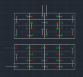
-> you use the Chargery BMS outputs to disconnect charge/load in case of undervoltage / overvoltage as illustrated in the below picure

newbostonconst
Solar Enthusiast
- Joined
- Sep 24, 2019
- Messages
- 1,005
The battery layout in this diagram above is crap. There are better was to do it....Just a FYI, I wouldn't want someone to follow it. You shouldn't need diagonal bus bars.
The rest of the layout appears fine.
The rest of the layout appears fine.
newbostonconst
Solar Enthusiast
- Joined
- Sep 24, 2019
- Messages
- 1,005
Steve_S
Offgrid Cabineer, N.E. Ontario, Canada
That's a V3 Manual image.
replaced in new manuals.

replaced in new manuals.
Your description is generally a correct interpretation of how I have my system set up, but the diagram is not. Since I don't have a separate Load and Charge bus, I use one main battery cutoff relay whose coil is fed by two SSRs in series with my 24V bus as shown in the attached diagram. The SSRs are fed by the BMS Charge and Discharge controllers. I did this because I didn't want to connect the BMS outputs across a 24V bus to directly feed the coil, and to minimize the current draw on the Chargery BMS outputs to keep the coil energized (note my diagram does not show the wiring to the Multiplus, just the main battery cutoff relay).Hello @bdbugbee , OK understand (I thiink). Chargery BMS have 2 relay outputs : "Charge controller" + "Discharge controller"
-> you plug this 2 outputs to the AUX + Temp sensor Multiplus 2 I/O
and also
-> you use the Chargery BMS outputs to disconnect charge/load in case of undervoltage / overvoltage as illustrated in the below picure
View attachment 24053

Similar threads
- Replies
- 18
- Views
- 504
- Replies
- 3
- Views
- 411
- Replies
- 46
- Views
- 2K
- Replies
- 32
- Views
- 2K
- Replies
- 2
- Views
- 199