If you used 280AH cells, they can discharge at 280A for 1 hour o take 140A Charge for 2 hours.
The JKBMS default is too low and many settings by default are wrong... Now fixed in their new Inverter Edition BMS.
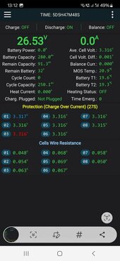
Review your
advanced settings against these shown below.
This can be up to 3.650
Best to keep this within 0.075v difference
<- Allows for low sag when cells are low.
<--- Never Ever let the cells hit 2.500 you can Brick the BMS. and harm cells.
<--! CHANGE TO 3.40 or better 3.42 and just let the work happen where it should.
<-- What the cells can take, regardless of what charger is pushing.
<<<----------
<<< DEFAULTS ARE WRONG !
<<< Change them !
<<<
<<<
<<<
<<<
<<<
<<<
<<<
<<< ---------
Also review your CHarging Profiles to ensure you are not pushing anything too hard that could (and will) cause High Volt Disconnects and more... Below is a conservative profile that works very well.
All equipment MUST BE Voltage Corrected & Calibrated (VERY IMPORTANT)
Divide Values X2 for 12V. Multiply X2 for 48V.
Bulk / Absorb: 27.6V (Absorb for 45 minutes (3.45vpc)
(some call this boost)
Equalize: OFF
Float 27.5V (3.437vpc)
MIn Volts: 21.2V (2.650vpc)
Max Volts: 28.6V (3.575vpc)
Rebulk Voltage: 25.6 (3.200vpc)
End Amps/TailCurrent: *1 (Triggers change from Absorb to Float)
(*1): End Amps is calculated: (100AH X 0.05 = 5A or 280AH X 0.05 = 14A.
EndAmps = TailCurrent
Coulumbic Efficiency / Battery Status Meter Efficiency for LFP = 99%.
This gets the bank charged to full with high amps (Constant Current Constant Voltage) and then float (Constant Voltage, Variable Current) tops off so the cells are at 3.437Vpc. I
! Do Not forget to adjust for Voltage Offsets between Actual Voltage @ Battery Terminal & at Solar Controller.
BMS With Active Balancing should be set to start Active Balancing at 3.420V or possibly lower to 3.410 so that the cells can balance out at the top and not affect the charging process.
Very Special NOTE: Floating & Saturating to 3.437vpc, accounts for the Voltage Settling post Charge of any kind which actually brings the cells to just below 3.400Vpc.
EDIT - July 7 2022.
 Voltage Corrected & Calibrated (VERY IMPORTANT)
- Midnite Solar Classics SCC's can be programmed for OFFSETS.
- Not all are capable so to adjust values it will have to be in charging values AS WELL as your Inverter/Charger.
- Even 0.1 Volt offset Can & Will affect operations
The simplest Way
Use 2 or 3 Decimal Accurate DVOM/DMM.
While SCC is Charging, Measure the Real Voltage coming out of the SCC and write it down, Same for the Inverter/Charger @ its BATT Terminal.
When Batts are in a + Charge (NOT when Discharging) measure the Voltage @ its/their Battery Terminal Lugs.
There WILL be some variances but there is always some Line Loss between these devices, Most important is what is going into the BATT.
Check your notes from each test. That Differential in Voltage must be Compensated for !
Take that Voltage Offset and apply it to the SCC, either an Offset Function or by the Charge Settings
IE, Assume SCC to Batt Terminal is 0.1V and you are Charging, Bulk/Absorb/Float Adjust the values UP. IE If Absorbing @ 27.6V increase that to 27.7V to compensate and the other Values as well. DO NOT FORGET to do the same for Low Voltage Disconnect !
The Inverter Needs two values;
The Charging Voltage offset applied as Above You got that value in your tests above. With SCC Charging.
Low Voltage Disconnect. MUST BE Measured when No SCC Charging is happening and the inverter is drawing from BATT only. It will be different than when SCC is charging the batts. Use that to adjust for Low Volt Disconnect ! Or you may get a Late Disconnect @ Low Volts making the disconnect lower than you set. NOT A GOOD THING !
Lastly, be aware that every Fuse/Breaker, Lug & Batt terminal adds to Voltage Drop collectively due to resistance.
EDIT - SOLAR CHARGING NOTE: (my own setup)
Array 1 is 2080W using 8x 260W Panels arranged in 4S-2P, connected to a Midnite Classic 200 that produces 79A for a 24V Bank.
Array 2 is 2370W using 6x 395W Panels arranged in 2S-3P, connected to a Midnite Classic 150 that produces 94A for my 24V Bank.
With High quality SCC's such as Victron, Midnite etc don't really require massive arrays to provide good charge. Yes there is a cost difference but think of 6 Panels or 18 ? to get 100A charging... SCC's are NOT all the same, especially those high voltage combined ones.


")