silverstone
Solar Enthusiast
- Joined
- May 3, 2022
- Messages
- 1,041
I finally started up my 2 first Batteries (2 x 16s x 280Ah cells) yesterday charging with one Inverter at around 3kW (approx 30A / battery).
Today Charging them with all Inverters at around 50-60 A / battery.
I read that the LiFePo4 Cells Voltage vs SOC is very flat in a wide SOC region. I also read that it got VERY steep near fully charged and approx. below 10% SOC.
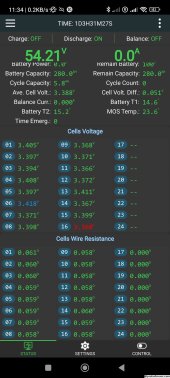
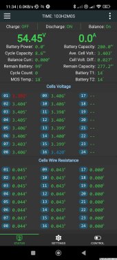
I just didn't expect it to be *that* steep. In a matter of seconds at 60A, one cell went from 3.52V to 3.63V as if she was going to the moon . That triggered JK BMS High Voltage Disconnect.
Since then:
- I increased balance starting voltage to 3.42V (from Steve_S 3.36V) - Based on Andy's Offgridgarage, too low of a Balance Start Voltage could CREATE unbalance. This might be indeed the case here
- I reduced OVPR Overvoltage Protection Recovery Voltage to 3.42V (from Steve_S 3.525V) - I got something like 25 disconnect + 25 reconnect events within an hour or so, where i didn't supervise what was going on ... Simply because the JK BMS would allow charge again too early on.
I used mostly Steve_S configuration from

 diysolarforum.com
Inverter was set to 55.2V float and (initially) 56.4V absorbtion/equalization and 100A charge. Now set to 55.2V float, 56.0V absorbtion/equalization and 40A charge current.
I did NOT Top-balance the pack. This might well be the main issue. I completed the assembly and really, I didn't have much energy left to fiddle around with all the busbars.


The first cell in the second pack at 3.39V ... that's probably because it started at a lower SOC compared to the other 15 (3.23V vs 3.28V IIRC).
My plan would be to "top" balance the pack by charging with a small 5A source (possibly even set lower to 2A ?) and let it run overnight. That should (hopefully) be enough for the Active Balancer to manage to balance the pack during charge. Surely more manageable 5A than 50A ....
Any other ideas ? Originally I thought like I had a runaway cell but maybe it's just a lack of top balancing .
.
Today Charging them with all Inverters at around 50-60 A / battery.
I read that the LiFePo4 Cells Voltage vs SOC is very flat in a wide SOC region. I also read that it got VERY steep near fully charged and approx. below 10% SOC.
I just didn't expect it to be *that* steep. In a matter of seconds at 60A, one cell went from 3.52V to 3.63V as if she was going to the moon
Since then:
- I increased balance starting voltage to 3.42V (from Steve_S 3.36V) - Based on Andy's Offgridgarage, too low of a Balance Start Voltage could CREATE unbalance. This might be indeed the case here
- I reduced OVPR Overvoltage Protection Recovery Voltage to 3.42V (from Steve_S 3.525V) - I got something like 25 disconnect + 25 reconnect events within an hour or so, where i didn't supervise what was going on ... Simply because the JK BMS would allow charge again too early on.
I used mostly Steve_S configuration from

Steve_S-Tech: My Final Config for Midnite Classic SCC & JKBMS' w/ Large Bank (works amazingly well) Includes Charge Profile & BMS Config
INTRO: I have debated posting this for a while until I got everything tweaked in and working as best as possible. The End Result is Gobsmackingly Good ! I cannot speak for other SCC and such as each is different & unique in their own ways BUT this may likely be a Good Reference. Civility &...
Inverter was set to 55.2V float and (initially) 56.4V absorbtion/equalization and 100A charge. Now set to 55.2V float, 56.0V absorbtion/equalization and 40A charge current.
I did NOT Top-balance the pack. This might well be the main issue. I completed the assembly and really, I didn't have much energy left to fiddle around with all the busbars.


The first cell in the second pack at 3.39V ... that's probably because it started at a lower SOC compared to the other 15 (3.23V vs 3.28V IIRC).
My plan would be to "top" balance the pack by charging with a small 5A source (possibly even set lower to 2A ?) and let it run overnight. That should (hopefully) be enough for the Active Balancer to manage to balance the pack during charge. Surely more manageable 5A than 50A ....
Any other ideas ? Originally I thought like I had a runaway cell but maybe it's just a lack of top balancing


